Profile Edge
The Profile Edge tool finds an edge on a profile, searching from left to right. The tool's settings help fit the edge point when multiple potential edges are in the profile. You can configure the tool to locate a step or a corner (that is, for cases where there is no clear step in the profile but instead a smooth slope), as well as rising or falling steps.
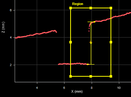
Step height of a step
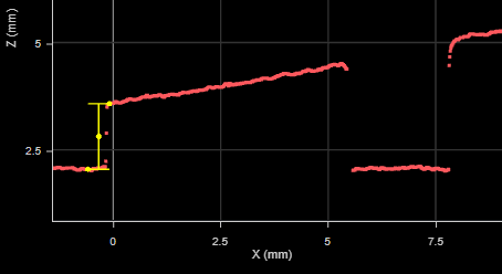
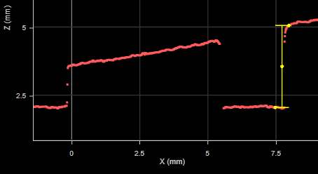
After the tool locates an edge, it returns the position (X and Z) of the edge. For steps, it also returns the step height.
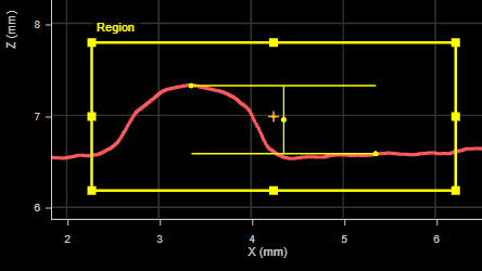
The tool can also generate a point geometric feature corresponding to the center of the step that Feature tools can take as input for measurement. For more information on Feature tools, see Feature Measurement.
For information on adding, managing, and removing tools, as well as detailed descriptions of settings common to most tools, see Tool Configuration.
Inputs
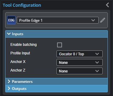
You configure the tool's inputs in the expandable Inputs section.

|
To use a measurement as an anchor, it must be enabled and properly configured in the tool providing the anchor. For more information on anchoring, see Measurement Anchoring. |
| Name | Description |
|---|---|
| Enable Batching |
For more information on arrays, batching, and aggregating, see Arrays, Batching, and Aggregation. |
|
Profile Input |
The data the tool applies measurements to or processes. |
|
Anchor X or Anchor Z |
The X or Z measurement of another tool that this tool uses as a positional anchor. Positional anchors are optional. |
Parameters
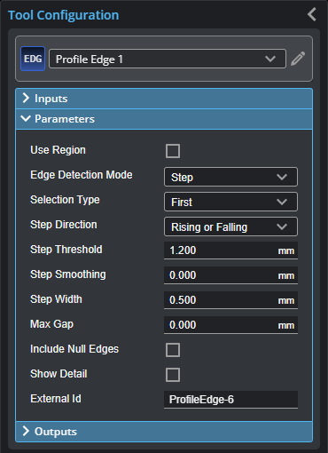
You configure the tool's parameters in the expandable Parameters section.
| Parameter | Description |
|---|---|
| Enable Batching |
For more information on arrays, batching, and aggregating, see Arrays, Batching, and Aggregation. |
|
Use Region |
When enabled, displays Region parameters (see below). When disabled, the tool uses all data. |
|
Region |
The region to which the tool's measurements will apply. For more information, see Regions. |
|
Edge Detection Mode |
One of the following: Step or Corner. Step: Searches for steps on each path profile. When the edge detection mode is set to Step, you must set several additional parameters. For more information, see Step Edge Detection Mode Parameters. Corner: Searches for slopes on each path profile. When the edge detection mode is set to Corner, you must set the Corner Type parameter. For more information, see Corner Edge Detection Mode Parameters. |
|
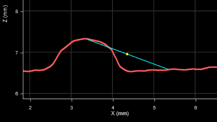
Show Detail |
When the parameter is enable, the tool displays a line joining the points used to calculate the edge. This can be useful when viewing the edge's center point on a step. Note that enabling this parameter can have an effect on processing. For high frequency scanning, be sure to disable it.
|
|
External ID |
The external ID of the tool that appears in GoHMI Designer. For more information, see GoHMI and GoHMI Designer. |

| Parameter | Description |
|---|---|
|
Corner Type |
Determines the corner type the tool searches for. One of the following: Best: Selects the greatest step in the profile data. Left: Selects the left-most step in the profile data. Right: Selects the right-most step in the profile data. Top: Selects the step that is the highest in the profile data. Bottom: Selects the step that is lowest in the profile. |
Outputs
All tools provide measurements, geometric features, or data as outputs.
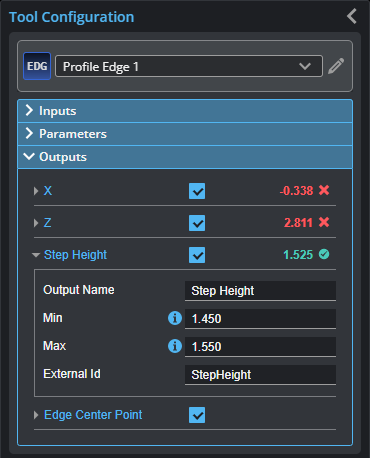
Outputs section with a measurement expanded to show user-configurable decision min/max fields and an external ID
You configure the Min and Max parameters by expanding the measurement in the Outputs section. In order for a measurement to return a Pass decision, the measurement must be between maximum and minimum values; the range is inclusive.
| Measurement |
|---|
|
X Z These measurements return the X and Z position of the edge point, respectively. The edge point is located half-way between the upper and lower data points of the step. |
|
Step Height Returns the height of the step on the profile. Only available if Edge Detection Mode is set to Step. |
| Type | Description |
|---|---|
| Edge Center Point |
The edge point. |
|
|
For more information on geometric features, see Geometric Features. |