Surface Direction Filter
The Surface Direction Filter helps exclude unwanted data points based on their “orientation” (the polar angle relative to surrounding data points) in 3D space, for example, data points resulting from reflections. The tool can provide better results than median or height based filters. The tool lets you define up to 16 regions to which the filtering is applied.
For example, in the following scan data, noise appears to the right of two surface mount components on a PCB (pink areas). In this case, the "direction" of the noise is roughly 75 to 85 degrees, relative to Z.
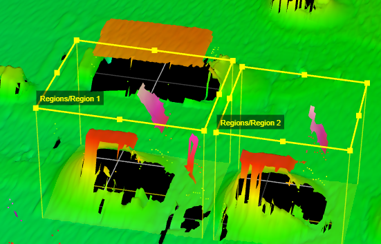
Surface before direction filtering.
In the following scan data, the tool has removed the noise.
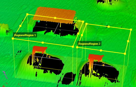
Surface after direction filtering.
Note that the tool's filtering parameters apply to all enabled regions. To apply different filtering parameters, you can add additional instances of the tool and chain them together, setting the input of subsequent instances to the output of the preceding instance.
For information on adding, managing, and removing tools, as well as detailed descriptions of settings common to most tools, see Tool Configuration.
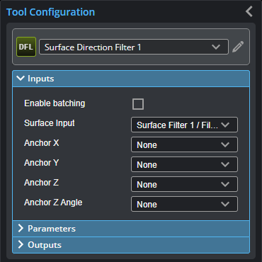
Inputs
You configure the tool's inputs in the expandable Inputs section.

|
To use a measurement as an anchor, it must be enabled and properly configured in the tool providing the anchor. For more information on anchoring, see Measurement Anchoring. |
| Name | Description |
|---|---|
| Enable Batching |
For more information on arrays, batching, and aggregating, see Arrays, Batching, and Aggregation. |
|
Surface Input |
The data the tool applies measurements to or processes. |
|
Anchor X Anchor Y Anchor Z |
The X, Y, or Z measurement of another tool that this tool uses as a positional anchor. Positional anchors are optional. |
| Anchor Z Angle |
The Z Angle measurement of another tool to use as a rotational anchor for this tool. Rotational anchors are optional. |
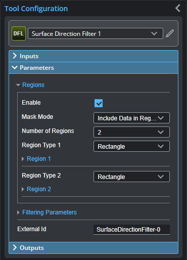
Parameters
You configure the tool's parameters in the expandable Parameters section.
The following illustrates the angle parameters that control which data points are excluded in scan data:

The number of neighboring points shown above is for illustrative purposes only.
| Parameter | Description |
|---|---|
|
Regions |
When expanded, displays the region- and mask-related settings. |
|
Enable |
Enables regions and displays the region- and mask-related settings (see below). |
|
Mask Mode Number of Regions Region Type {n} Region {n} |
When you enable regions (see above), the tool displays additional settings related to the region type. For details on the regions supported by this tool and their settings, see Flexible Regions. For general information on regions and the difference between standard and "flexible" regions, see Regions. |
|
Filtering Parameters |
When expanded, displays the filtering parameters the tool uses. |
|
Min Z Angle Max Z Angle |
The minimum and maximum acceptable angles around the Z axis of the XY projection of the normal of the surface surrounding a data point, where 0 degrees is defined as positive X and positive rotation is clockwise around the Z axis. |
|
Min Polar Angle Max Polar Angle |
The minimum and maximum acceptable angles of the normal of the surface surrounding a data point with respect to the Z axis. |
|
Smooth Size |
A mean filter applied to the surface data before calculating the normals in order to avoid abrupt normal changes due to noise. |
|
Noise Removal |
Eliminates noise that can be introduced by the tool's normal calculation. |
|
Preserve Data Outside Region |
When enabled, data outside the regions is preserved in the output. Otherwise, only the data in the regions is output. |
|
External ID |
The external ID of the tool that appears in GoHMI Designer. For more information, see GoHMI and GoHMI Designer. |
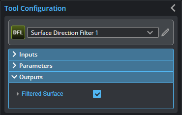
Outputs
All tools provide measurements, geometric features, or data as outputs.
| Type | Description |
|---|---|
|
Filtered Surface |
The surface after filtering. |