Surface Opening
The Opening tool locates rounded, rectangular, and rounded corner openings. The opening can be on a surface at an angle to the sensor.

|
The tool does not search for or detect the feature. The tool expects that the feature, conforming reasonably well to the defined parameters, is present and that it is on a sufficiently uniform background. |

The tool uses a complex feature-locating algorithm to find a hold and then return measurements. For a detailed explanation of the algorithm the tool uses, see Opening Algorithm. The behavior of the algorithm can be adjusted by changing the tool's parameters.
The tool can separate out background information that appears inside the opening. It can also detect a slot that only partially appears in the data.
The shape of the opening is defined by its type and its nominal width, length, and radius.
The orientation defines the rotation around the normal of the alignment plane.

Measurement Panel
For information on adding, managing, and removing tools, as well as detailed descriptions of settings common to most tools, see Tool Configuration.
Measurement Region
The center and the two sides and ends of the opening must be within the measurement region, even if Partial Detection is enabled.

Opening Algorithm
The Opening tool processes the data in three phases: Search, Measure, and Filter.
Search phase - The tool searches for coarse data transitions (edge data) and performs a coarse fitting of the opening shape (specified by the orientation angles and the nominal dimensions) to determine the most likely candidate. If Tilt Correction is enabled, the algorithm uses the flat surface in the measurement region to estimate the orientation of the part.
Measure phase - A more rigorous edge detection algorithm is applied to precisely determine the edges around the feature. Edge detection at this stage will reject outliers and noise. The algorithm requires opposite sides and ends to be associated with a comparable number of edge pixels, with the weaker side or end having at least 25% of the stronger.
The set of refined edges is then used to locate and inspect the feature. If the Reference Regions setting is enabled, the edges are also used to calculate the location of the reference regions.

Filter phase - The detected location and dimensions are compared to the nominal and tolerance settings. If the refined feature falls within the measurement region and its measurements fit within the specified tolerance, the results are reported. If not, an invalid result is returned.
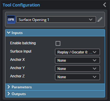
Inputs
You configure the tool's inputs in the expandable Inputs section.
|
|
To use a measurement as an anchor, it must be enabled and properly configured in the tool providing the anchor. For more information on anchoring, see Measurement Anchoring. |
| Name | Description |
|---|---|
| Enable Batching |
For more information on arrays, batching, and aggregating, see Arrays, Batching, and Aggregation. |
|
Surface Input |
The data the tool applies measurements to or processes. |
|
Anchor X Anchor Y Anchor Z |
The X, Y, or Z measurement of another tool that this tool uses as a positional anchor. Positional anchors are optional. |
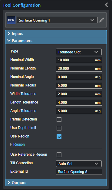
Parameters
You configure the tool's parameters in the expandable Parameters section.
| Parameter | Description |
|---|---|
|
Type |
One of the following: Rounded Slot, Rectangle. |
|
Nominal Width |
Nominal width of the opening. |
|
Nominal Length |
Nominal length of the opening. |
|
Nominal Angle |
Nominal angle of the opening. The default orientation is the length of the opening along the X axis.
|
|
Nominal Radius |
Nominal radius of the opening ends. If the opening type is set to rectangular, the radius setting is disabled. The opening has an oval shape if the radius is equal to ½ of the width. The opening is a rounded rectangle when the radius is less than ½ of the width.
|
|
Width Tolerance Length Tolerance Angle Tolerance |
The maximum variation from the nominal width, length, and angle (+/- from the nominal value). |
|
Partial Detection |
Enable if only part of the opening is within the measurement region. If disabled, the opening must be completely in the region of interest for results to be valid. |
|
Use Depth Limit Depth Limit |
When Use Depth Limit is enabled, data below the value set in Depth Limit (relative to the surface) is excluded from the |
| Use Region | If enabled, displays an expandable region section where you define the region. |
|
Region |
The region to which the tool's measurements will apply. For more information, see Regions. |
|
Use Reference Region Reference Type Reference Region {n} |
When Use Reference Region is enabled, the tool uses reference regions to calculate the Z position of the
When the Reference Regions setting is disabled, the tool measures the
With one or more reference regions, the algorithm calculates the Z positions as the average values of the data within the regions. When you place the reference region manually, all of the data is used, whether the data is inside or outside the opening. You should place the reference region carefully. |
|
Tilt Correction |
Tilt of the target with respect to the alignment plane. Autoset: The tool automatically detects the tilt. The measurement region to cover more areas on the surface plane than other planes. Custom: You must enter the X and Y angles manually in the X Angle and Y Angle parameters (see below). |
|
X Angle Y Angle |
The X and Y angles you must specify when Tilt Correction is set to Custom. You can use the Surface Plane tool's X Angle and Y Angle measurements to get the angle of the surrounding surface, and then copy those measurement's values to the X Angle and Y Angle parameters of this tool. |
|
External ID |
The external ID of the tool that appears in GoHMI Designer. For more information, see GoHMI and GoHMI Designer. |


Outputs
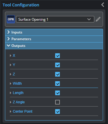
Outputs section with a measurement expanded to show user-configurable decision min/max fields and an external ID
You configure the Min and Max parameters by expanding the measurement in the Outputs section. In order for a measurement to return a Pass decision, the measurement must be between maximum and minimum values; the range is inclusive.
| Measurement | Illustration |
|---|---|
|
X Determines the X position of the opening's center. |
|
|
Y Determines the Y position of the opening's center. |
|
|
Z Determines the Z position of the opening's center. |
|
|
Width Determines the width of the opening. |
|
|
Length Determines the length of the opening. |
|
|
Z Angle Determines the angle (rotation) around the normal of the alignment plane. |
|


| Type | Description |
|---|---|
| Center Point |
The center point of the opening. The Z position of the center point is at the Z position of the surrounding surface. |
|
|
For more information on geometric features, see Geometric Features. |