Surface Roughness
The Surface Roughness tool generates measurements of surface roughness. The following measurements are available:
- Sa
- Sq
- Sp
- Sv
- Sz
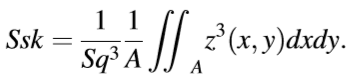
- Ssk
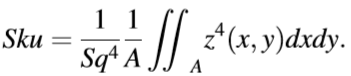
- Sku
The tool offers five filter operations that can be enabled or disabled individually as required. The following filters are available:
-
Filling Gaps: Designed to fill any holes in the surface and on the edge while trying to keep the surface as natural as possible.
-
Remove Form: Offers both homogeneous and inhomogeneous polynomial filters from 1 to 8 orders.
-
Remove Outliers: Used to remove outliers which are defined as a percentage of points in relation to the total number of points at the furthest distance from the height center.
-
Gaussian and Cubic Spline filters: The tool offers Gaussian and Cubic Spline filters as standard filters for removing waviness. The Gaussian filter is used by default. The tool offers 4 conventional "end-effect" treatment options that are recommended by ISO 16610-28.
-
The tool offers Gaussian filters with small Cut-Off wavelength (3 µm) as a low pass filter.
For information on adding, managing, and removing tools, as well as detailed descriptions of settings common to most tools, see Tool Configuration.
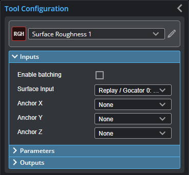
Inputs

|
To use a measurement as an anchor, it must be enabled and properly configured in the tool providing the anchor. For more information on anchoring, see Measurement Anchoring. |
| Name | Description |
|---|---|
| Enable Batching |
For more information on arrays, batching, and aggregating, see Arrays, Batching, and Aggregation. |
|
Surface Input |
The data the tool applies measurements to or processes. |
|
Anchor X Anchor Y Anchor Z |
The X, Y, or Z measurement of another tool that this tool uses as a positional anchor. Positional anchors are optional. |
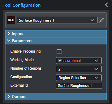
Parameters
The following parameters are in the expandable Parameters section in the tool's configuration.
| Parameter | Description |
|---|---|
|
Enable Processing |
When enabled, the tool starts performing measurements. |
|
Working Mode |
The tool's working mode. One of the following:
|
| Number of Regions | Sets the number of regions to be calculated, currently up to 16. (Two additional regions are reserved for calibration.) |
|
An expandable section displayed when Working Mode is set to Check Parameters. The tool gives the summed mean values and the recorded sample number after each measurement. For mirror calibration, the mean values of the background noise of Sa and Sq and the number of measurements are returned. For roughness calibration, the nominal values of Sa and Sq must be specified before the measurement starts. The mean scaling value and the number of measurements are returned. |
|
| Configuration |
Lets you choose which region to configure in the expandable Region {n} section. Regions are independent. The two regions for mirror and roughness calibration targets are suspended after the specified number of evaluation regions, that is, after changing the number of evaluation regions, the settings for “Mirror” and “Roughness” must be checked again. |
| Region | An expandable section containing the parameters for the region selected in Configuration. |
| Use Region | If enabled, uses the region you define. |
|
Number of Regions |
Select the number of regions to be calculated, currently up to 18. Two regions are available for selection (the last 2 are reserved for calibration). |
|
Fill Gaps Mode |
Set to Linear Interpolation to fill any holes in the surface and on the edge while trying to keep the surface as natural as possible. |
|
Remove Form |
Check to remove form from the surface with homogeneous or inhomogeneous polynomial filter. |
|
Polynomial Order |
Order of polynomial function. |
|
Remove Outliers |
The outlier is defined here as a percentage of points in relation to the total number of points at the furthest distance from the height center. When using the integrated histogram curve, the outliers outside the threshold range are replaced by the corresponding limit values, which are calculated by the points within the threshold range. |
|
Remove Waviness |
Check to remove waviness using Gaussian or Cubic Spline filter. |
|
Filter Type |
Choose Gaussian filter or Spline Filter. |
|
End Effect |
Methods for dealing with end-effects. One of the following:
|
|
Use Low Pass Filter Low Pass Cut-off |
Check Use Low Pass Filter to use low pass filter with cut-off wavelength defined in Low Pass Cut-off. |
|
Margins |
Custom margin distance. |
|
Output Parameters |
Some combination of measurement outputs can be selected. Dynamic measurement management is used. |
|
External ID |
The external ID of the tool that appears in GoHMI Designer. For more information, see GoHMI and GoHMI Designer. |
Outputs
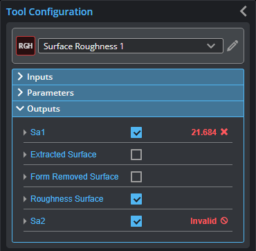
Outputs section with a measurement expanded to show user-configurable decision min/max fields and an external ID
You configure the Min and Max parameters by expanding the measurement in the Outputs section. In order for a measurement to return a Pass decision, the measurement must be between maximum and minimum values; the range is inclusive.
| Measurement | Formula |
|---|---|
|
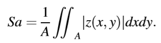
Sa {n} Arithmetical mean height, which is the difference in height of each point compared to the arithmetical mean of the surface. |
|
|
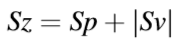
Sz {n} Maximum height, which is defined as the sum of the largest peak height value and the largest pit depth value within the defined area. |
|
|
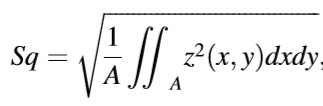
Sq {n} Root mean square height, which is equivalent to the standard deviation of heights. |
|
|
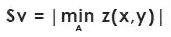
Sv {n} Maximum pit Height, which is the absolute value of the height of the largest pit within the defined area. |
|
|
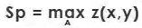
Sp {n} Height of the highest peak within the defined area. |
|
|
Sku {n} Kurtosis, which is a measure of the sharpness of the roughness profile. |
|
|
Ssk {n} Skewness, which represents the degree of bias of the roughness shape (asperity). |
|
| Type | Description |
|---|---|
|
Extracted Surface |
Surface data after filling gaps. |
|
Form Removed Surface |
Surface data after subtracting the polynomial pattern. |
|
Roughness Surface |
Surface data after a high pass filtering.s |
Calibration Procedure
| 1. | Deactivate "Enabled Processing" to get into the editing mode. |
| 2. | Use "Check Parameters" in the "Working Mode" option to check the last calibration. |
| 3. | Use Reset Parameters to ensure that all parameters from the last calibration are reset. If no correction is used, this action can also be used. |
| 4. | Change the "Working Mode" to "Mirror calibration". |
| 5. | Editing position and size of the region and other settings. |
| 6. | Use the input data measured with a mirror. |
| 7. | Activate "Enabled Processing" to start the mirror calibration. |
| 8. | Repeat the measurement as necessary. The tool gives the summed up mean value of background noise and the recorded sample number after each measurement. 25 measurements is recommended, but there is no upper limit to the number of measurements. |
| 9. | Deactivate "Enabled Processing" to get into the editing mode. |
| 10. | Change the "Working Mode" to "Roughness calibration". |
| 11. | Enter the nominal values of Sa and Sq of the calibration target. Depending on requirements, Sa, Sq can be calculated separately or together, (since the two correlate very well, a mean value of the correction factor can be formed if the two are activated). |
| 12. | Editing position and size of the region and other settings. |
| 13. | Use the input data measured with a roughness calibration target. |
| 14. | Activate "Enabled Processing" to start the roughness calibration. |
| 15. | Repeat the measurement as necessary. The tool gives the summed up mean value of correction factor and the recorded sample number after each measurement. 25 measurements is recommended, but there is no upper limit to the number of measurements. |
| 16. | It is assumed that a job file is created after the calibration, so the information is preserved in the job file. |
Roughness Calculation Procedure
-
Deactivate "Enabled Processing" to get into the editing mode.
-
Select the number of regions to be calculated, currently up to 20 - 2 regions are available for selection (the last 2 are reserved for calibration).
-
Configure individual regions. The default settings correspond roughly to the settings when using Mountains Map, so only the region should be set. Otherwise, all available configurations for each region should be set according to specification.
-
Activate the measurements and output surfaces.
-
Activate "Enabled Processing" to start the calculation.