Profile Closed Area
The Closed Area tool determines the cross-sectional area within a region using point cloud data (that is, with Enable uniform spacing disabled in the Acquire > Scan page > Scan Mode panel) from a dual- or multi-sensor system.
The tool renders a polygon corresponding to the profile in the data viewer. Use this polygon to decide whether the tool can correctly calculate an acceptable representation of the profile. Minor gaps in the profile are permitted; the size of these gaps is configurable.
For information on adding, managing, and removing tools, as well as detailed descriptions of settings common to most tools, see Tool Configuration.
Inputs
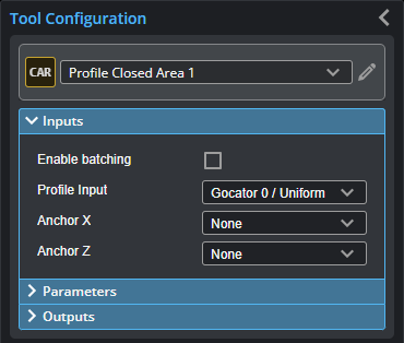
You configure the tool's inputs in the expandable Inputs section.

|
To use a measurement as an anchor, it must be enabled and properly configured in the tool providing the anchor. For more information on anchoring, see Measurement Anchoring. |
| Name | Description |
|---|---|
| Enable Batching |
For more information on arrays, batching, and aggregating, see Arrays, Batching, and Aggregation. |
|
Profile Input |
The data the tool applies measurements to or processes. This tool can optionally take an array as input. For more information, see Arrays, Batching, and Aggregation. |
|
Anchor X or Anchor Z |
The X or Z measurement of another tool that this tool uses as a positional anchor. Positional anchors are optional. |
Parameters
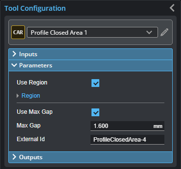
You configure the tool's parameters in the expandable Parameters section.
| Parameter | Description |
|---|---|
|
Use Region |
Indicates whether the tool uses a user-defined region. If this option is not checked, the tool uses data from the entire active area. |
|
Region |
The region to which the tool's measurements will apply. For more information, see Regions. |
|
Use Max Gap |
Indicates whether the tool uses the Max Gap setting (see below). |
|
Max Gap |
The maximum gap allowed between any two profile points on the contour of the target, in millimeters. In the following illustration of a profile, if the gap were greater than the value set in Max Gap, the tool would return an invalid value.
|
|
External ID |
The external ID of the tool that appears in GoHMI Designer. For more information, see GoHMI and GoHMI Designer. |

Outputs
All tools provide measurements, geometric features, or data as outputs.
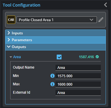
Outputs section with a measurement expanded to show user-configurable decision min/max fields and an external ID
You configure the Min and Max parameters by expanding the measurement in the Outputs section. In order for a measurement to return a Pass decision, the measurement must be between maximum and minimum values; the range is inclusive.
All outputs provide an external ID (available by expanding the output in the Outputs panel) for optional use in GoHMI Designer. For more information, see GoHMI and GoHMI Designer.
| Measurement | Illustration |
|---|---|
|
Area Measures the cross-sectional area within a region using data from a dual- or multi-sensor system. |
|
