Profile Part Detection

|
Profile sensors can produce Surface data for applications where a transport system such as a conveyor continuously feeds discrete parts or material under a sensor. Typically, you will set a sensor to Surface mode on the Scan page, set Surface generation type to Continuous, and then configure the part detection parameters on the Scan page. The sensor will then output Surface data for each part it detects. The Profile Part Detection tool uses the same parameters available with continuous generation Surface mode, but also provides diagnostics that can be useful for troubleshooting. After troubleshooting part detection using this tool, you can copy the settings from the tool to the Scan page. The diagnostics are output as measurements by the tool. Note that the Profile Part Detection has a Frame of Reference parameter not available when using continuous Surface generation. For more information on Surface generation, see Surface Generation. Remember that when using this tool, the sensor is set to Profile mode. |
The Profile Part Detection tool takes a series of profiles as input, analyzes the characteristics of each profile based on the configuration of the tool's parameters, and identifies discrete objects and then outputs them as Surface data. Surface measurements can then be performed on each object. This method of surface generation is typically used when a transport system such as a conveyor continuously feeds parts or material under a sensor. The parts or material must have a distinguishable start and stop edge. The sensor continuously generates surfaces of parts that are detected under the sensor.
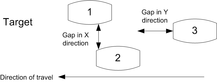
Multiple parts can pass through the laser at the same time and will be individually tracked. Parts can be separated along the laser line (X axis), in the direction of travel (Y axis), or by gated external input.
|
|
Gocator also lets you isolate and then measure parts using one of two Surface measurement tools (for more information on these tools, see Surface Blob and Surface Segmentation). |
Part detection can be performed when Source on the Acquire > Scan page in the Trigger panel is set to Time or Encoder. To use the Time trigger source, the travel speed must be calibrated. To use the Encoder trigger source, the encoder resolution must be calibrated.
|
|
The Profile Part Detection tool is only available when Enable uniform spacing (resampling) is checked: the tool does not support point cloud profile data. |
In addition to a Part Surface output, the tool also returns the Point geometric feature of center of the detected part, and several measurement tool that you can use as diagnostics (for example, to see the number of parts accepted, the number of parts rejected and why, the part's length, and so on). For a complete list of the diagnostics, see below.
When working with previously recorded Profile scan data, you can set the FPS replay setting to a value high enough that parts are displayed in a reasonable amount of time. You can also optionally enable the Continuous Loop to loop through parts continuously.
|
|
In order to see a detected part's Surface data when the Profile Part Detection tool is selected in the list of added tools, the Part Surface must be selected in the list of outputs or pinned below the data viewer. |
For information on adding, managing, and removing tools, as well as detailed descriptions of settings common to most tools, see Tool Configuration.
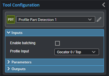
Inputs
You configure the tool's inputs in the expandable Inputs section.
| Name | Description |
|---|---|
| Enable batching |
When Enable Batching is checked, the tool takes an array as input and processes each profile in the array individually. |
|
Profile Input |
The source of profiles for the tool. |
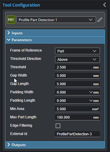
Parameters
You configure the tool's parameters in the expandable Parameters section.
| Parameter | Description |
|---|---|
|
Height threshold |
Determines the height threshold for part detection. The setting for Threshold Type (see above) determines if parts should be detected above or below the value in Threshold. Above is typically used to prevent the belt surface from being detected as a part when scanning objects on a conveyor. |
|
Threshold direction |
Determines if parts should be detected above or below the height threshold. |
|
Gap Width Gap Length |
Gap Width and Gap Length determine the minimum separation between objects on the X and the Y axis, respectively. If parts are closer than the gap interval, they will be merged into a single Surface output.
|
|
Padding Length |
These parameters are useful when processing part data with third-party software such as HexSight, Halcon, etc. Padding Width and Padding Length control the amount of additional scan data output in the X and Y directions, respectively. The padding can contain data points that were outside the height threshold and excluded from the initial part detection. |
|
Min Area |
Determines the minimum area for a detected part. Set this value to a reasonable minimum in order to filter out small objects or noise. |
|
Max Length |
Determines the maximum length of the part object. When the object exceeds the maximum length, it is automatically separated into two parts. |
|
Edge Filter
|
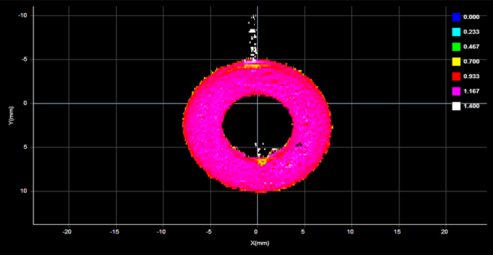
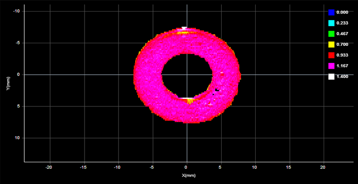
When Edge Filter is enabled, an Edge Filter expanding section is displayed that contains the settings described below. Part scans sometimes contain noise around the edges of the target. This noise is usually caused by the sensor’s light being reflected off almost vertical sides, rounded corners, etc. (The following screenshots are from a G2 sensor.)
Edge Filter disabled (scan shows reflection noise)
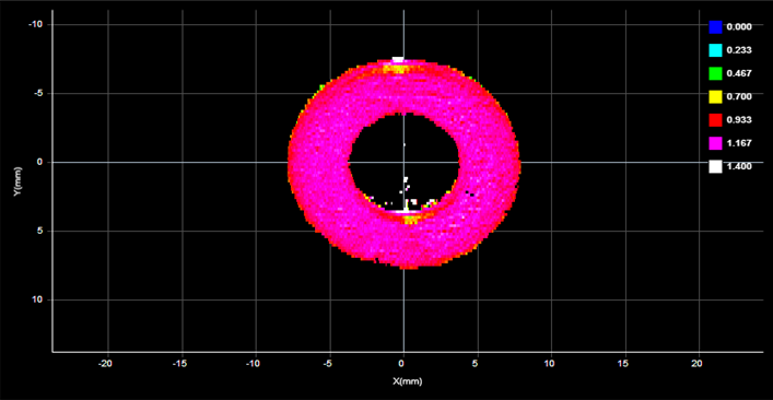
Edge Filter enabled (reflection noise eliminated or reduced)
Edge Filter enabled, Keep Interior enabled |
|
Keep Interior |
The Keep Interior setting limits filtering to the outside edges of the target. |
|
Edge Width Edge Length |
The Edge Width and Edge Length settings represent the size of the filter on the X axis and the Y axis, respectively. |
|
External ID |
The external ID of the tool that appears in GoHMI Designer. For more information, see GoHMI and GoHMI Designer. |
Outputs
One of the most common issues when setting up part detection is that surface data is not generated after scanning the target or targets. The Profile Part Detection tool's measurements provide information on the status of the part detection engine. You can use these measurements to diagnose why the tool is not detecting parts.
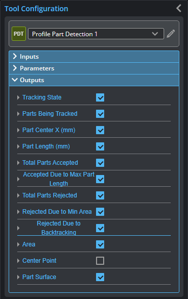
You configure the Min and Max parameters by expanding the measurement in the Outputs section. In order for a measurement to return a Pass decision, the measurement must be between maximum and minimum values; the range is inclusive.
| Measurement |
|---|
|
Tracking State Part detection state for largest currently tracking part. The possible values returned by are the following: 0: Not In Part 1: In Part, Min area not achieved 2: In Part, Min area achieved 3: In Gap, Min area not achieved 4: In Gap, Min area achieved |
|
Parts Being Tracked The number of parts the engine is currently tracking. |
|
Part Center X The center of the partial part, midway between the minimum X and maximum X detected for the part. |
|
Part Length The length of the part. In cases of backtracking, the number decreases. |
|
Total Parts Accepted The number of parts that meet the part detection criteria (based on the configuration of the tool's parameters). |
|
Due to Max Part Length The number of parts accepted because they have reached the value in the Max Part Length parameter (see above). If too many parts are being accepted, increase Max Part Length. |
|
Total Parts Rejected The number of parts that fail to meet the part detection criteria. |
|
Rejected Due to Min Area The number of parts rejected because they are below the value in the Min Area parameter (see above). If too many parts are being rejected, reduce Min Area. |
|
Rejected Due to Backtracking The number of parts rejected due to backtracking, for example, when the user reverses the direction of the transport mechanism while the sensor is actively scanning a part. |
|
Area The area of the current part. |
| Type | Description |
|---|---|
| Center Point |
The center point of the detected part. |
|
|
For more information on geometric features, see Geometric Features. |
| Type | Description |
|---|---|
| Part Surface |
The Surface data of the detected part. |