Raw Profile Matching

|
The Raw Profile Matching tool takes unresampled profile data as input (the Enable uniform spacing setting is disabled on Acquire > Scanners). |
The Raw Profile Matching tool lets you align a profile to a "master" template profile you create in the tool (a "golden template"), compensating for movement of the target from frame to frame. As a result, you can perform measurements on a "stabilized" profile.
The tool returns measurements that represent differences between the profile and the master, letting you perform simple defect detection and location from within the tool.
The tool also outputs an aligned profile that other Profile measurement tools can use as input (via their Stream parameter).
In the data viewer, the profiles are rendered using different colors:
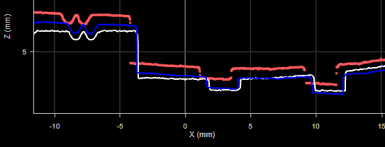
The master profile is rendered in white. The aligned profile is rendered in blue. The current profile is rendered in red.
Note that in the image above, the tool is performing only a rough alignment to ensure that the different profiles are clearly visible for illustration purposes. Typically, the blue aligned profile will be on top of the white master profile.
For information on adding, managing, and removing tools, as well as detailed descriptions of settings common to most tools, see Tool Configuration.
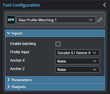
Inputs
You configure the tool's inputs in the expandable Inputs section.
|
|
To use a measurement as an anchor, it must be enabled and properly configured in the tool providing the anchor. For more information on anchoring, see Measurement Anchoring. |
| Name | Description |
|---|---|
| Enable Batching |
For more information on arrays, batching, and aggregating, see Arrays, Batching, and Aggregation. |
|
Profile Input |
The data the tool applies measurements to or processes. |
|
Anchor X or Anchor Z |
The X or Z measurement of another tool that this tool uses as a positional anchor. Positional anchors are optional. |
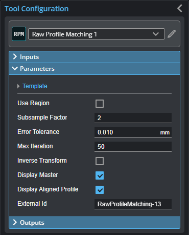
Parameters
You configure the tool's parameters in the expandable Parameters section.
| Parameter | Description |
|---|---|
| Template | When expanded, displays File and Operation parameters. |
|
File |
A list of templates available to the tool to use as a master profile for alignment and comparisons. Use the Operation parameter to add and remove templates. |
|
Operation |
Provides operations related to profile template files (masters). One of the following:
|
|
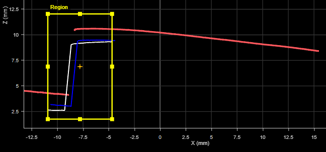
Use Region |
Indicates whether the tool uses a user-defined region to perform matching. (The tool uses only the data profile and master data in this region to perform matching.) If this option is not checked, the tool performs matching using data from the entire active area. For more information on regions, see Regions. |
|
Match Region |
When Use Region is enabled, provides settings for the size and position of the region in which the matching (alignment) is performed.. Master comparison measurements however are applied to the entire profile (current profile and master). For example, in the following image, the tool limits matching to the data in the match region. But the measurement (Max Height Difference in this case) is calculated on the data outside the region.
(The dashed lines are added to illustrate the hidden aligned profile and master.) |
|
Subsample Factor |
The sampling interval of the input profile point cloud.
|
|
Error Tolerance |
The difference tolerance for the master comparison.
|
|
Max Iteration |
The maximum number of iterations the tool uses to perform iterative closest point (ICP). The tool stops iterating once the input profile is considered within the error tolerance (see above). |
|
Inverse Transform |
When enabled, inverts the output transformation.
|
|
Display Master |
Displays the Master template (white profile). |
|
Display Aligned Profile |
Displays the aligned profile (blue profile). |
|
External ID |
The external ID of the tool that appears in GoHMI Designer. For more information, see GoHMI and GoHMI Designer. |
Outputs
All tools provide measurements, geometric features, or data as outputs.
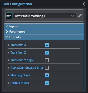
Outputs section with a measurement expanded to show user-configurable decision min/max fields and an external ID
You configure the Min and Max parameters by expanding the measurement in the Outputs section. In order for a measurement to return a Pass decision, the measurement must be between maximum and minimum values; the range is inclusive.
| Measurement |
|---|
|
Transform X Transform Z The distance the profile has shifted on the X and Z axis after alignment to the master, respectively. |
|
Transform Y Angle The rotation of the profile around the Y axis after alignment. |
|
Root Mean Squared Error The root mean squared error of the alignment. |
|
Matching Score Returns a value between 0 and 1 representing the percentile of standard deviation of a difference profile (calculated by subtracting the current profile from the master) from the tolerance. |
| Type | Description |
|---|---|
|
Aligned Profile |
The profile aligned to the master. |