Surface Stud
The Stud tool measures the location and radius of a stud.

|
The tool does not search for or detect the feature. The tool expects that the feature, conforming reasonably well to the defined parameters, is present and that it is on a sufficiently uniform background. |
The tool uses a complex feature-locating algorithm to find a hold and then return measurements. For a detailed explanation of the algorithm, see Stud Algorithm.
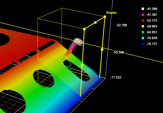
The location of the stud is defined at either the stud tip or the stud base. The tip is the intersection of the stud axis and the top of the stud; the base is the intersection of the stud axis and the surrounding plane.

The stud shape is defined by the tip height and base height. The base and tip heights specify where the shaft with the nominal radius begins and ends.

Measurement Panel
For information on adding, managing, and removing tools, as well as detailed descriptions of settings common to most tools, see Tool Configuration.
Stud Algorithm
The Stud algorithm measures the stud in three steps: searching for the tip, finding the reference plane, and shaft fitting. Note that the tip and the side of the stud must be within the measurement region.
Searching for the tip - The algorithm looks for the approximate location of the tip. If Auto-Tilt is enabled, the algorithm uses the flat surface around the tip to estimate the orientations of the part. The approximate tip is the location of the highest (maximum Z) pixel after correction for the nominal tilt angle.
Finding the reference plane - The reference regions are positioned using the approximate tip, the nominal angle values, and the nominal stud length. Compared to the hole/opening, misplaced stud reference regions are more likely to cause a failure to produce any measurement.
Shaft fitting - The shaft region is determined based on the approximate tip position, the nominal angles, the reference plane position, and the stud nominal size parameters. Shaft fitting is successful if the algorithm can fit at least three circles with the stud diameter along the shaft. Fitting each circle requires sufficient data along the top portion the shaft. Because of occlusions, the bottom of the shaft is often not visible to the sensor and the algorithm is designed to handle this situation.
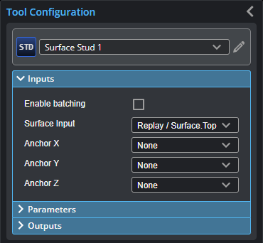
Inputs
|
|
To use a measurement as an anchor, it must be enabled and properly configured in the tool providing the anchor. For more information on anchoring, see Measurement Anchoring. |
| Name | Description |
|---|---|
| Enable Batching |
For more information on arrays, batching, and aggregating, see Arrays, Batching, and Aggregation. |
|
Surface Input |
The data the tool applies measurements to or processes. |
|
Anchor X Anchor Y Anchor Z |
The X, Y, or Z measurement of another tool that this tool uses as a positional anchor. Positional anchors are optional. |
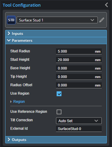
Parameters
The following parameters are in the expandable Parameters section in the tool's configuration.
| Parameter | Description |
|---|---|
|
Stud Radius |
Expected radius of the stud. |
|
Stud Height |
Expected height/length of the stud. |
|
Base Height |
The height above the base surface that will be ignored when the (truncated) cone is fitted to the stud data. |
|
Tip Height |
The height from the top of the surface that will be ignored when the (truncated) cone is fitted to the stud data. |
|
Radius Offset (Radius measurement only) |
The distance from the tip of the stud from which the radius is measured. |
|
Use Region |
When enabled, displays Region parameters (see below). When disabled, the tool uses all data. |
|
Region |
The region to which the tool's measurements will apply. For more information, see Regions. |
|
Use Reference Region |
When enabled, displays the Reference Type setting. |
|
Reference Type |
The tool uses the reference regions to calculate the base plane of the stud. Reference regions are relative to the base of the stud. |
|
Tilt Correction |
Tilt of the target with respect to the alignment plane. Autoset: The tool automatically detects the tilt. The measurement region to cover more areas on the surface plane than other planes. Custom: You must enter the X and Y angles manually in the X Angle and Y Angle parameters (see below). |
|
X Angle Y Angle |
The X and Y angles you must specify when Tilt Correction is set to Custom. You can use the Surface Plane tool's X Angle and Y Angle measurements to get the angle of the surrounding surface, and then copy those measurement's values to the X Angle and Y Angle parameters of this tool. |
|
External ID |
The external ID of the tool that appears in GoHMI Designer. For more information, see GoHMI and GoHMI Designer. |
Outputs
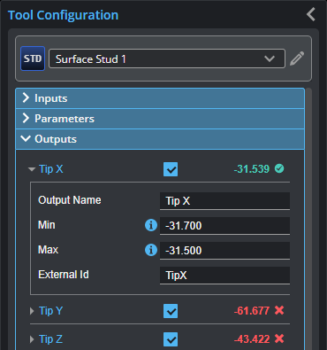
Outputs section with a measurement expanded to show user-configurable decision min/max fields and an external ID
You configure the Min and Max parameters by expanding the measurement in the Outputs section. In order for a measurement to return a Pass decision, the measurement must be between maximum and minimum values; the range is inclusive.
| Measurement | Illustration |
|---|---|
|
Tip X Determines the X position of the stud tip. |
|
|
Tip Y Determines the Y position of the stud tip. |
|
|
Tip Z Determines the Z position of the stud tip. |
|
|
Shaft X Determines the X position of the stud shaft. The position is defined with the parameter Radius Offset. |
|
|
Shaft Y Determines the Y position of the stud shaft. The position is defined with the parameter Radius Offset. |
|
|
Shaft Z Determines the Z position of the stud shaft. The position is defined with the parameter Radius Offset. |
|
|
Base X Determines the X position of the stud base. |
|
|
Base Y Determines the Y position of the stud base. |
|
|
Base Z Determines the Z position of the stud base. |
|
|
Radius Determines the radius of the stud. |
|


| Type | Description |
|---|---|
| Tip Point |
The center point of the stud tip. |
| Shaft Point |
The center point of the stud shaft. |
| Base Point |
The center point of the stud base. |
|
|
For more information on geometric features, see Geometric Features. |