Triggers
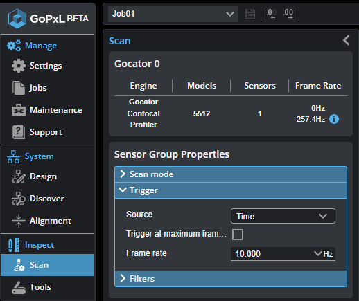
A trigger is an event that causes a sensor to take a single image. You configure triggers on the Acquire > Scan page.
When a trigger is processed, the sensor's laser or LED light strobes and the camera exposes to produce an image. The resulting image is processed inside the sensor to yield scan data.
The sensor can be triggered by one of the sources described below.
G2 and G5
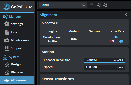
When using encoder triggering (G2 and G5), the current encoder resolution is displayed under the Source drop-down as a reference when setting trigger spacing.
To set the encoder resolution, go to the System > Alignment page and set the value in Encoder Resolution.
| Trigger Source | Description | ||
|---|---|---|---|
| Time |
Sensors have an internal clock that can be used to generate fixed-frequency triggers. The external input can be used to enable or disable the time triggers. |
||
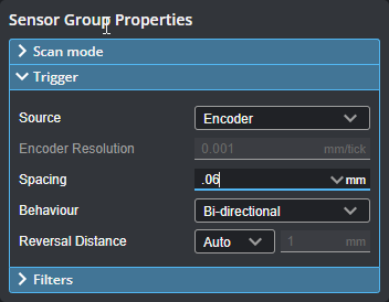
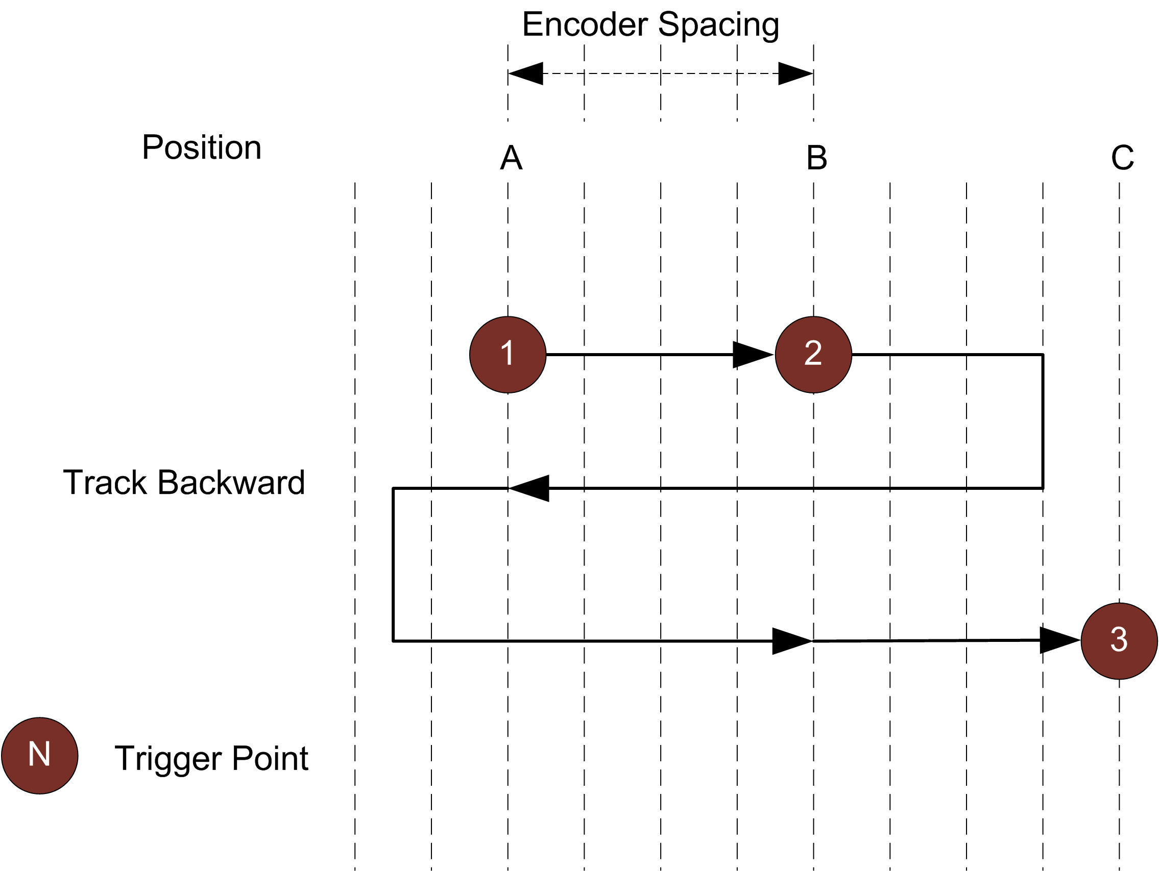
| Encoder |
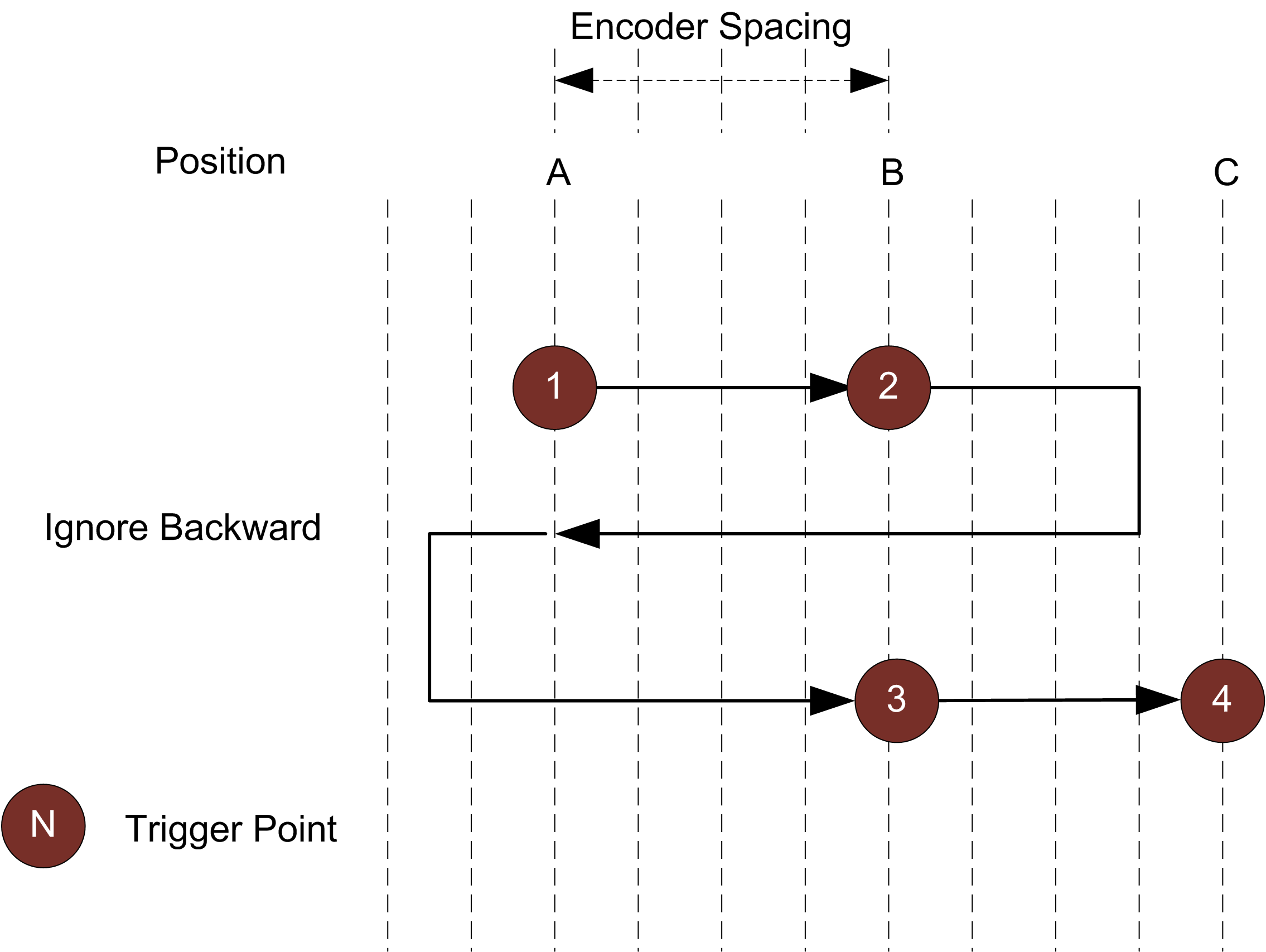
An encoder can be connected to provide triggers in response to motion. Three encoder triggering behaviors are supported. These behaviors are set using the Behavior setting. Track Backward A scan is triggered when the target object moves forward. If the target object moves backward, it must move forward by at least the distance that the target travelled backward (this distance backward is "tracked"), plus one encoder spacing, to trigger the next scan.
Ignore Backward A scan is triggered only when the target object moves forward. If the target object moves backward, it must move forward by at least the distance of one encoder spacing to trigger the next scan.
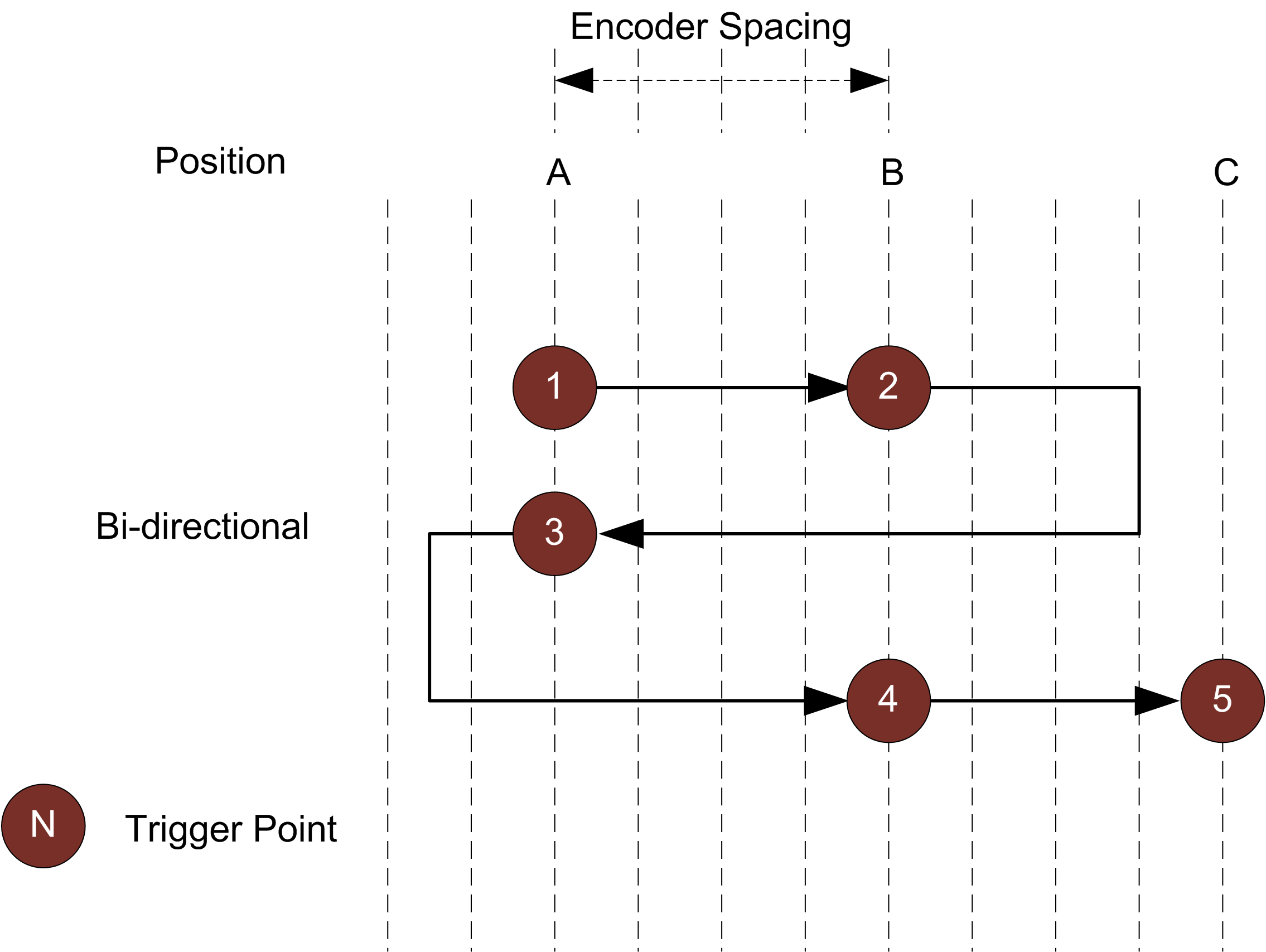
Bi-directional A scan is triggered when the target object moves forward or backward.
When triggers are received at a frequency higher than the maximum frame rate, some triggers may not be accepted. Use the Trigger Drops indicator in the Health panel on the Reports page to check for this condition; for more information, see Reporting. The external input can be used to enable or disable the encoder triggers. For information on the maximum encoder rate, see Maximum Encoder Rate.
|
||
| External Input |
A digital input can provide triggers in response to external events (for example, a photocell). The external input triggers on the rising edge of the signal. When triggers are received at a frequency higher than the maximum frame rate, some triggers may not be accepted. Use the Trigger Drops indicator in the Health panel on the Reports page to check for this condition; for more information, see Reporting. |
||
| Software |
A network command can be used to send a software trigger. For more information, Protocols (PLCs and other hardware). |

Trigger Settings
| Parameter | Trigger Source | Description |
|---|---|---|
|
Source |
All |
Selects the trigger source (Time, Encoder, External Input, or Software). |
|
Trigger at maximum frame rate |
Time |
When this is enabled, the frame rate locks to the maximum frame rate. |
|
Frame Rate |
Time |
Controls the frame rate. Fractional values are supported. For example, 0.1 can be entered to run at 1 frame every 10 seconds. |
|
Spacing |
Encoder |
Specifies the distance, along the Y axis, between triggers. Internally the sensor rounds the spacing to a multiple of the encoder resolution. |
|
Encoder trigger mode |
Encoder |
Specifies how the sensor is triggered when the target moves. Can be Track Backward, Ignore Backward, or Bi-Directional. For more information, see Encoder in Trigger source descriptions. |
| Reversal Distance |
Encoder |
When the Encoder trigger mode parameter is set to Bi-Directional, use this setting to ignore jitter or vibrations in your transport system by specifying what distance the target must travel before a direction change is triggered. One of the following: Auto: The distance is automatically set by multiplying the value in Spacing by 3. Custom: Set the distance (in millimeters). Various functions in the sensor depend on this value to explicitly determine the point where direction change is triggered. Set this value larger than the maximum vibrations you see in your transport system. |
| Auto Reversal Distance |
Encoder |
When encoder triggering is set to Bi-Directional, the sensor ignores jitter or vibrations in the transport system. When Auto Reversal Distance is enabled y the distance is automatically set by multiplying the value in Spacing by 3. When Auto Reversal Distance is disabled, set the desired value in Reversal Distance in millimeters. Various functions in the sensor depend on this value to explicitly determine the point where direction change is triggered. Set this value larger than the maximum vibrations you see in your transport system. |
| Reversal Distance |
Encoder |
The custom value to use when Auto Reversal Distance is disabled. |
|
Units |
External Input |
Specifies whether the trigger delay, output delay, and output scheduled command operate in the time or the encoder domain. The unit is implicitly set to microseconds with Time trigger source. |
| Trigger Delay | External Input |
Controls the amount of time or the distance the sensor waits before producing a frame after the external input is activated. This is used to compensate for the positional difference between the source of the external input trigger (for example, photocells) and the sensor. |