Profile Area
The Area tool determines the cross-sectional area within a region.

Profile Area tool with baseline set to the best-fitted line in Region 1
For information on adding, managing, and removing tools, as well as detailed descriptions of settings common to most tools, see Tool Configuration.
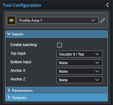
Inputs
You configure the tool's inputs in the expandable Inputs section.

|
To use a measurement as an anchor, it must be enabled and properly configured in the tool providing the anchor. For more information on anchoring, see Measurement Anchoring. |
| Name | Description |
|---|---|
| Enable Batching |
For more information on arrays, batching, and aggregating, see Arrays, Batching, and Aggregation. |
|
Top Input Bottom Input |
The data the tool applies measurements to or processes. This tool can optionally take a second, bottom input. |
|
Anchor X or Anchor Z |
The X or Z measurement of another tool that this tool uses as a positional anchor. Positional anchors are optional. |
Parameters
You configure the tool's parameters in the expandable Parameters section.

| Parameter | Description |
|---|---|
|
Type |
Object area type is for convex shapes above the baseline. Regions below the baseline are ignored. Clearance area type is for concave shapes below the baseline. Regions above the baseline are ignored. |
|
Baseline |
Baseline is the fit line that represents the line above which (Object clearance type) or below which (Clearance area type) the cross-sectional area is measured. When this parameter is set to Line, you must define a line in the Line parameter. See Fit Lines for more information on fit lines. When this parameter is set to X-Axis, the baseline is set to z = 0. |
|
Use Region |
When enabled, displays Region parameters (see below). When disabled, the tool uses all data. |
|
Region |
The region to which the tool's measurements will apply. For more information, see Regions. |
| Line |
When Baseline (see above) is set to Line, set this to one of the following: 1 Region or 2 Regions: Lets you set one or two regions. The tool uses the data in those regions to fit a line. All Data: The tool uses all of the data in the scan data. For more information on regions, see Regions). For more information on fit lines, see Fit Lines. |
|
External ID |
The external ID of the tool that appears in GoHMI Designer. For more information, see GoHMI and GoHMI Designer. |
Outputs
Most tools provide measurements, geometric features, or data as outputs.

Outputs section with a measurement expanded to show user-configurable decision min/max fields and an external ID
You configure the Min and Max parameters by expanding the measurement in the Outputs section. In order for a measurement to return a Pass decision, the measurement must be between maximum and minimum values; the range is inclusive.
| Measurement | Illustration |
|---|---|
|
Area Measures the cross-sectional area within a region that is above or below a fitted baseline. |
|
|
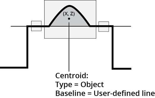
Centroid X Determines the X position of the centroid of the area. |
|
|
Centroid Z Determines the Z position of the centroid of the area. |


| Type | Description |
|---|---|
| Center Point |
The center point of the area. |
|
|
For more information on geometric features, see Geometric Features. |