Measurement Anchoring
The position of parts moving on a transport mechanism such as a conveyor typically changes from part to part in one or both of the following ways:
- along the X, Y, and Z axes
- around the Z axis (orientation angle)
When the position and angle variation between parts is minor—for example, when scanning electronic parts in trays—you can anchor one tool to one or more measurements from another tool to compensate for these minor shifts. As a result, GoPxL can correctly place the anchored tool's measurement regions on each part. This increases the repeatability and accuracy of measurements.

|
For cases where movement from part to part is more drastic, you can often use the Surface Pattern Matching tool to compensate. For more information, see Surface Pattern Matching. |
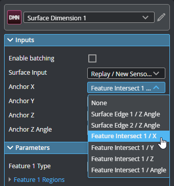
You set a tool's anchors in its Inputs section, by setting Anchor X, Anchor Y, Anchor Z, or Anchor Z Angle to the appropriate measurement from another tool:
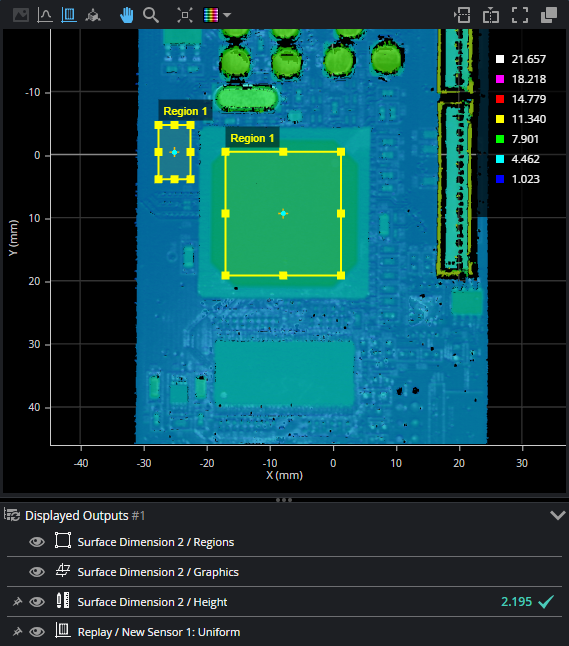
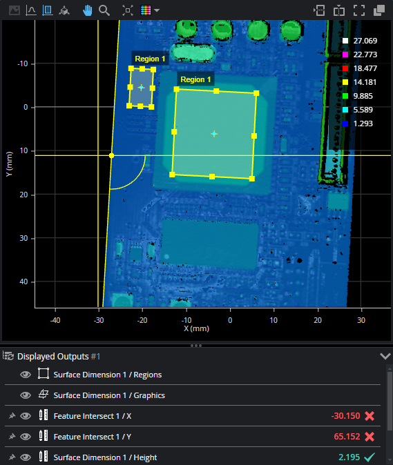
For example, the following shows a surface scan of a PCB. A Surface Dimension height measurement returns the height of a component in the measurement region relative to a nearby reference region; the height is between the measurement's thresholds and is a pass (the green value in the Displayed Outputs pane).
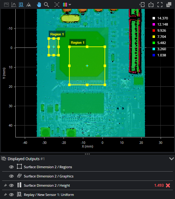
In the following scan, the part has shifted, but the measurement regions remain where they were originally configured, in relation to the sensor or system coordinate system, so the measurement returned is incorrect, and the measurement fails:
When you set any of a tool's anchor sources, an offset is calculated between the anchored tool and the anchor source. This offset is used for each frame of scanned data: the anchored tool's measurement region is placed in relation to the anchor source, at the calculated offset.
In the following image, after the Surface Dimension tool is anchored to the X and Y measurements from two Surface Edge tools (placed over the left and bottom edges of the PCB), GoPxL compensates for the shift—mostly along the X and the Y axis in this case—and returns a correct measurement, despite the shift.
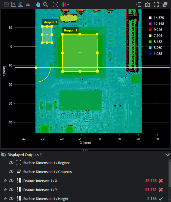
You can combine the positional anchors (X, Y, or Z measurements) with an angle anchor (a Z Angle measurement) for optimum measurement placement. For example, in the following scan, the part has not only shifted on the XY plane but also rotated around the Z axis. Anchoring the Surface Dimension tool to the Z Angle measurement of a Surface Edge tool compensates for the rotation, and the anchored tool returns a correct measurement.
|
|
If Z Angle anchoring is used with both X and Y anchoring, the X and Y anchors should come from the same tool. |
|
|
If Z Angle anchoring is used without X or Y anchoring, the tool's measurement region rotates around its center. If only one of X or Y is used, the region is rotated around its center and then shifted by the X or Y offset. |