Profile Bounding Box
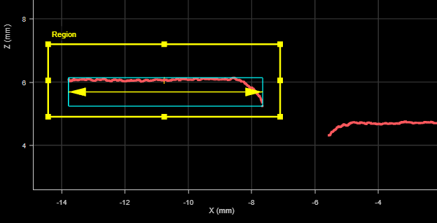
The Bounding Box tool provides measurements related to the smallest box that contains the profile (for example, X position, Z position, width, etc.).
The bounding box provides the absolute position from which the Position centroids tools are referenced.
For information on adding, managing, and removing tools, as well as detailed descriptions of settings common to most tools, see Tool Configuration.
Inputs
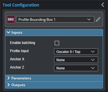
You configure the tool's inputs in the expandable Inputs section.

|
To use a measurement as an anchor, it must be enabled and properly configured in the tool providing the anchor. For more information on anchoring, see Measurement Anchoring. |
| Name | Description |
|---|---|
| Enable Batching |
For more information on arrays, batching, and aggregating, see Arrays, Batching, and Aggregation. |
|
Profile Input |
The data the tool applies measurements to or processes. This tool can optionally take an array as input. For more information, see Arrays, Batching, and Aggregation. |
|
Anchor X or Anchor Z |
The X or Z measurement of another tool that this tool uses as a positional anchor. Positional anchors are optional. |
Parameters
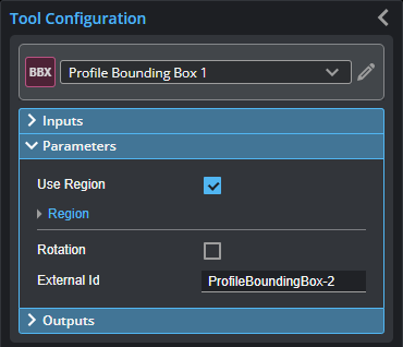
You configure the tool's parameters in the expandable Parameters section.
| Parameter | Description |
|---|---|
|
Use Region |
When enabled, displays Region parameters (see below). When disabled, the tool uses all data. |
|
Region |
The region to which the tool's measurements will apply. For more information, see Regions. |
| Rotation |
A bounding box can be vertical or rotated. A vertical bounding box provides the absolute position from which the part's Position centroid measurements are referenced. When enabled, allows rotation of the bounding box. Only displayed if Use Region is enabled. |
|
External ID |
The external ID of the tool that appears in GoHMI Designer. For more information, see GoHMI and GoHMI Designer. |
Outputs
Most tools provide measurements, geometric features, or data as outputs.
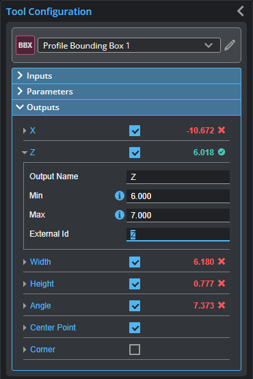
Outputs section with a measurement expanded to show user-configurable decision min/max fields and an external ID
You configure the Min and Max parameters by expanding the measurement in the Outputs section. In order for a measurement to return a Pass decision, the measurement must be between maximum and minimum values; the range is inclusive.
| Measurement | Illustration |
|---|---|
|
X Determines the X position of the center of the bounding box that contains the profile. The value returned is relative to the profile. |
|
|
Z Determines the Z position of the center of the bounding box that contains the profile. The value returned is relative to the profile. |
|
|
Width Determines the width of the bounding box that contains the profile. The width reports the dimension of the box in the direction of the minor axis. |
|
|
Height Determines the height (thickness) of the bounding box that contains the profile. |
|
|
Angle Determines the angle of the longer side of the bounding box around the Y axis, relative to the X axis. This measurement is only available if the Rotation parameter is enabled. |


| Type | Description |
|---|---|
| Center Point |
The center point of the bounding box. |
| Corner Point |
The lower left corner of the bounding box. |
|
|
For more information on geometric features, see Geometric Features. |