Pattern Editor
The pattern editor lets you modify patterns created in the Surface Pattern Matching tool (for more information on the tool, see Surface Pattern Matching). Although the patterns created in the Surface Pattern Matching tool will often result in good matches with your targets, you can use the pattern editor to improve the models, specifically by doing the following:
- Remove unwanted contours the Surface Pattern Matching tool has detected on edges in the scan data.
- Re-detect contours from the scan data using higher or lower levels of input image resolution (taken from the scan data) or contrast levels, compared to what the Surface Pattern Matching tool does internally.
- Identify certain contours as being required for a match to occur.
- Identify certain contours as being used to determine the position of a matched instance.

|
The Pattern Editor contains a Pattern setting (Surface or Image). Leave this set to Surface. The Image setting is reserved for future use. |
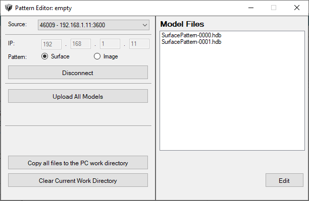
The editor uses two folders C:\GoTools\ on the PC it is running on.
GoPxLSurfacePatternMatchingSensor
When you choose a sensor or PC instance of GoPxL in the Source drop-down and click Connect, the editor empties this folder and copies any model files on the source into the folder. For this reason, if you have previously worked on model from this folder, make sure you have uploaded any changed models to the sensor or PC instance. The models in this folder are listed in the Model Files until you switch Source to PC Work Directory, or empty it by clicking Clear Sensor Work Directory.
The folder is referred to as the "Sensor Work Directory" in the editor.
GoPxLSurfacePatternMatching
This is called the "PC Work Directory" in the editor. You typically use this folder to transfer model files between sensors or PC instances of GoPxL. Also, because it is only emptied if you manually do it by clicking Clear PC Work Directory, it may be better to work from this folder. To get models in this folder, you first connect to a source and then click Copy all files to the PC work directory.
To see the files in this folder, switch Source to "PC Work Directory".
The pattern editor is available in the GoPxL Utilities package (14631-x.x.x.x_SOFTWARE_GoPxL_Utilities.zip, in the Tools\Pattern Editor folder. You can find the package on LMI's Product Downloads page (https://lmi3d.com/product-downloads/).
Launching the Pattern Editor
The first time you run the pattern editor, it may take longer to launch, as it will register certain DLLs required by the application.
The pattern editor can work with model files that come from an unaccelerated sensor or from a PC instance of GoPxL (which may or may not be accelerating a sensor). In all cases, the editor works with copies of the files in working folders in the local PC file system.
The Pattern Editor application
| Name | Description |
|---|---|
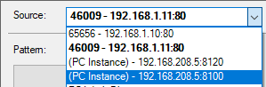
| Source |
The source from which the editor fetches model files.
The currently connected sensor is displayed in bold in the Source list.
The list contains the following types of entries:
Sensor Sensors are listed with their serial number followed by their IP address.
PC Instances Instances of GoPxL running on the PC are identified by "(PC Instance)", followed by their IP address.
PC Work Directory This is a local directory (C:\GoTools\GoPxLSurfacePatternMatching) that you typically use to transfer model files between sensors and PC instances of GoPxL. |
| Pattern | Leave this set to Surface. |
| Connect / Disconnect |
Connects to the source in Source. Note that connecting to a sensor deletes all models in the sensor working folder (C:\GoTools\SurfacePatternMatchingSensor) and then downloads the models currently on the sensor to that folder. For this reason, if you have modified models with the Pattern Editor, make sure to upload them before disconnecting and reconnecting. To fetch any models you have created on-sensor after connecting, disconnect using the Disconnect button, and then reconnect. |
| Upload All Models |
Uploads the models from the GoPxLSurfacePatternMatchingSensor local folder to the connected source (to a sensor or a PC instance of GoPxL). |
| Edit | Opens the selected model in the model editor; you can also double-click a model in the list to edit it. For more information, see Overview of the Editor. |
|
Copy all files to the PC work directory Copy all files to the sensor work directory |
Copies files between the PC Work Directory and the Sensor Work Directory. The name of this button depends on whether Source is set to PC Work Directory, or to a sensor or PC instance of GoPxL. |
|
Clear Sensor Work Directory Clear PC Work Directory |
Removes all models from the local working folder. The name of this button depends on whether Source is set to PC Work Directory, or to a sensor or PC instance of GoPxL. When you clear the sensor work directory, you are only deleting the files locally, not on the sensor or PC instance. |
By right-clicking on a model in the list of models, you can perform the operations listed below.
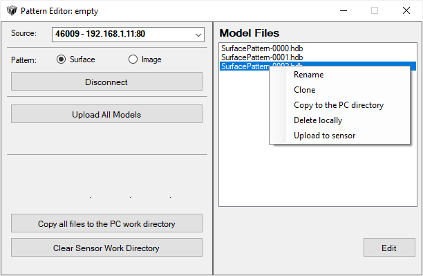
Rename: Renames the model.
Clone: Makes a copy of the selected model using the name you provide.
Copy to the PC directory / Copy to the sensor directory: Copies the model to a local directory.
Delete locally: Deletes the model from the GoPxLSurfacePatternMatchingSensor folder. Not displayed when Source is set to "PC Work Directory".
Upload to sensor: Uploads the model to the connected sensor.
Overview of the Editor
After clicking Edit in the pattern editor helper application, the selected model opens in the editor window.

| Element | Description | |
|---|---|---|
|
1 |
Model Creation pane |
Settings related to contour detection and feature selection. After configuring these settings, or resizing the model's bounding box (green dotted line), you must rebuild the model using the Build Model button. |
|
2 |
Model Contents |
The list of the features in a model (contours used in recognition and location of an instance). Note that some model contents (reference points and some settings in the Parameters tab) are not currently supported by the Surface Pattern Matching tool. |
|
3 |
Save and discard buttons |
Used to apply changes to a model, revert to the model’s original state when it was loaded, and so on. |
|
4 |
Outline, Detail, and Both tabs |
The editor tabs that show the Outline and Detail levels of the model. The Both tab shows both levels together, but you can't edit models on this tab. |
Models
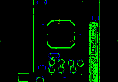
Models are made up of features selected from the source contours detected either by the Surface Pattern Matching tool or by the model editor itself (if you rebuild the model using the Build Model button). The features are used to identify and locate instances in the scan data.
Contours, and the features selected from the contours for use in recognizing and locating an instance, work on two “coarseness” levels: the Outline level and the Detail level.
Outline: Used to quickly identify potential instances of a pattern in scan data. The Outline level is the "coarse" level of contours / features. The features at this level can be less stable, as they are not used to calculate the location of the instance. For example, a label whose position might change from frame to frame or a hole whose size might change from frame to frame could be kept at the Outline level.
Detail: Used to confirm whether an instance is in fact valid and to refine its location. The Detail level is the "fine" level of contours / features. The features at this level must be more stable and rigid with respect to one another. For this reason, given Surface scan data, include features that are all on the same plane to ensure that their positions will not be unstable due to parallax or other scanning issues. Furthermore, features on a part that might vary in size from frame to frame, or change position (such as a label), should be excluded.
That said, the Outline and Detail levels will often be similar in terms of which features are included.
You can edit (add and remove) features at these levels separately, in the Outline and Detail panels in the main editor window. For more information on adding and removing features, see Adding and Removing Features Manually.
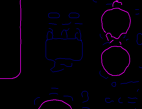
In the editor, “unused” contours (those not selected to take part in instance recognition or locating) are indicated with dark blue paths. Features (contours selected to take part in instance recognition or locating) are indicated with either magenta paths (at the Outline level) or with green paths (at the Detail level); the features in a model are listed in the Model Contents pane.
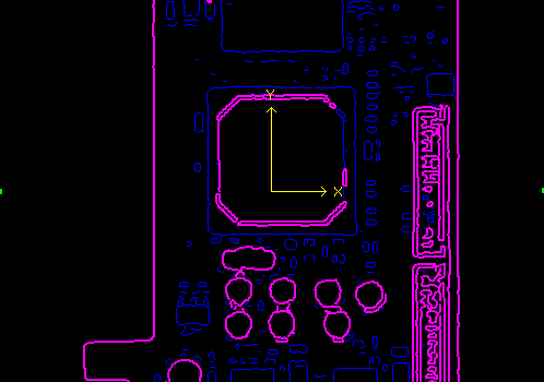
Dark blue unused contours and magenta features at the Outline level.
Dark blue unused contours and green features at the Detail level.
|
|
In the Surface Pattern Matching tool, only the Detail level of features is displayed. |
Adding and Removing Features Manually
You can manually add features to a model from the source contours, or remove features currently in a model, at both the Outline and Detail levels. This can be useful if the model produced by the Surface Pattern Matching tool includes features related to parts of targets that could change or be present/absent from frame to frame. You should only include features that are constant from frame to frame.
|
|
Adding and removing features works in the same way in the Outline and Detail tabs. |
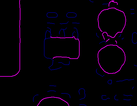
To add a feature from a source contour, double-click a dark blue contour in either the Outline or Detail tab and click Add or press the Insert key on your keyboard.
Dark blue unused contour (contours already added as features in the model are magenta).
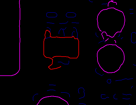
Contour selected by double-clicking it.
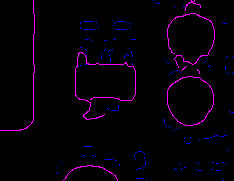
Contour added as a feature in the model (magenta).
If you single-click a dark blue unused contour, it turns cyan and lets you select segments of the contour.
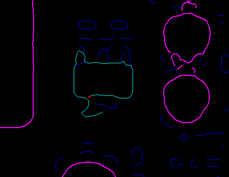
Contour highlighted in cyan with a selected segment (red).
Pressing the Ctrl key on your keyboard and clicking another segment selects a portion of the cyan path.
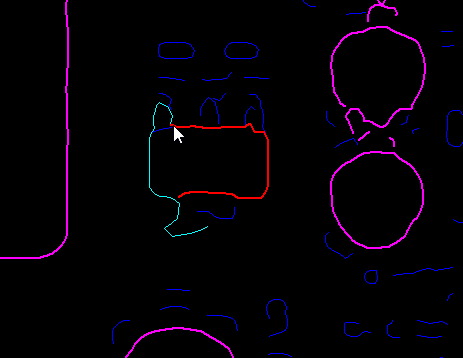
Clicking Add or pressing the Insert key on your keyboard adds the segment of the contour as a feature to the model.
After adding a feature, it is added to the list of features on the Feature tab in the Model Contents panel. Do not press the build button after adding or removing features, or you will lose the modifications that were just made. You must however save the changes; for more information, see Saving and Discarding Changes.
To remove a feature, click a magenta or green path in the editor to select it and click Delete or press the Delete key on your keyboard. After removing a feature, it is removed from the list of features on the Feature tab in the Model Contents panel. You do not need to build the model, but must save the changes; for more information, see Saving and Discarding Changes.
After adding a feature to a model or removing a feature from a model, you should analyze the model by clicking Analyze Model. Make note of any errors in the Messages panel.
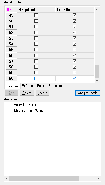
No error messages after clicking Analyze Model.
Setting Required and Locating Features
In the list of features in the Model Contents pane, you can indicate that a feature is “required” or that it is used to calculate the location of an instance by checking the appropriate checkbox next to the feature.
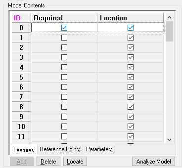
When Required is checked for a feature, it must be found by the Surface Pattern Matching tool in order for an instance to be identified.
When Location is checked for a feature, the Surface Pattern Matching tool uses the feature to calculate the location of instances. If a feature’s location is not checked, it is only used for instance recognition. An example of the latter is a tag or label glued to an object. Although the label's contours (it's shape or what is written on it) might be unique enough to help recognize an instance, it's position on the object (that is, relative to the other features) might vary in its position from frame to frame. For this reason, it might be useful for instance recognition, but not for determining the location of the object.
Model Creation Settings and Rebuilding
The Surface Pattern Matching tool uses internally fixed settings to detect contours in the scan data and then select features from those source contours. In the pattern editor, you can increase or decrease the contour detection levels, change the contrast threshold, and so on, and then rebuild the model. This can be useful if the Surface Pattern Matching tool’s internal settings do no produce the right amount of source contours and subsequently features.
The settings described here are found in the Model Creation section of the model editor.
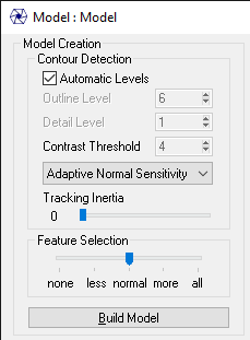
After making changes to any of these settings, you must rebuild the model by clicking Build Model, and then save the changes. You should also click Analyze Model after rebuilding a model. Pay special attention to messages in the Messages pane at the bottom of the editor to make sure there are no errors. For more information on saving changes, see Saving and Discarding Changes.
Coarseness Levels
By default, the pattern editor uses automatically determined contour coarseness values (at both the Outline and Detail levels) to detect contours in the scan data image. If you uncheck Automatic Levels, you can change the Outline Level and Detail Level values to generate more or fewer contours, from which you can then select features that more reliably represent your target.

The Outline Level and Detail Level values range from 1 to 16. At the lowest value, contours are detected in a full-resolution version of the image based on the scan data, which results in more contours from which to choose features. At higher values, contours are detected in a reduced-resolution version of the image based on the scan data: the resolution is reduced by the setting’s value, which results in fewer contours being detected. Note that Detail Level must be less than or equal to Outline Level.
Thresholds
You can adjust the level of sensitivity the pattern editor uses to detect contours in the scan data image.

By default, the sensitivity is set to Adaptive Normal Sensitivity, but you can set it to one of the following adaptive sensitivity levels, or to a fixed threshold value (see below).
Adaptive High Sensitivity: Results in more low-contrast contours, but also noise.
Adaptive Low Sensitivity: Results in strongly defined contours and eliminates noise, but may miss important contour segments.
If you set the dropdown to Fixed Value, you can then set a fixed threshold in Contrast Threshold. The Contrast Threshold value corresponds to the minimum step required to detect corners. A lower value generates more contours when you rebuild the model, but may also result in noise.
Tracking Inertia
Setting the Tracking Inertia slider to 1 closes small gaps in the source contours, connecting contours that might otherwise be broken into smaller sections.
![]()
Feature Selection
This setting ranges from none to all, which determines which features the pattern editor selects from the detected contours and adds to the model when you rebuild it. You should use none (which adds no features to the model) if you want to manually add features to the model from the detected contours. The normal setting tries to add the most appropriate features to the model; use this setting with simple to moderately complex parts. The all setting adds all detected contours as features to the model; only use this with very complex parts, such as electronic parts.
Saving and Discarding Changes
After making changes to a model (either adding or removing features, or re-detecting contours by clicking Build Model), you must do the following:
| 1. | In the model editor, at the bottom of the window, click Apply or OK. |
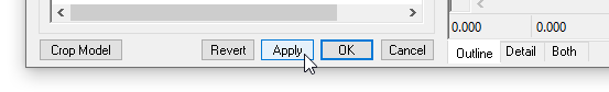
Clicking Apply leaves the model editor open. Do this if you want to continue working on a model (for example, if you want to test the model in Gocator before closing the model).
Clicking OK closes the model editor.
| 2. | In the pattern editor helper application, click the model you were working on, and click Save Model. |
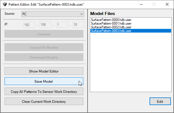
The model is saved to the working folder.
|
|
After making changes to a model, you must re-load the pattern in the instance of Surface Pattern Matching to see the changes. |
Before saving changes (either by clicking Apply or OK), you can revert the model to its initial state by clicking Revert.
Miscellaneous
Reference points, which you can create in the pattern editor on the Reference Points tab in the Model Contents panel, are not currently supported by the Surface Pattern Matching tool.
The Surface Pattern Matching tool does not currently support the custom shading area (on the Parameters tab in the Model Contents panel).
You can change the region of the model by resizing the green bounding box (or setting its dimensions in the Bounding Area section in the model editor) and rebuilding the model. After resizing and rebuilding the model to the desired region, you can use the Crop Model button to reduce the size of the final model surface, and reduce the pattern file size.
In the Show section in the model editor, you can hide the scan data to see only the contours and features by unchecking Image. Note that the Dim / Normal / Bright options below Image only apply to intensity data.