Profile Panel
The Panel tool provides Gap and Flush measurements.
The Panel tool uses a complex feature-locating algorithm to find the gap or calculate flushness and return measurements. The behavior of the algorithm can be adjusted by changing the tool's parameters. For a detailed explanation of the algorithm, see Gap and Flush Algorithms.

|
You must make sure that there are enough data points to define the edge in the profile, by properly setting up exposure, etc. If not, the algorithm will not function. |
For information on adding, managing, and removing tools, as well as detailed descriptions of settings common to most tools, see Tool Configuration.
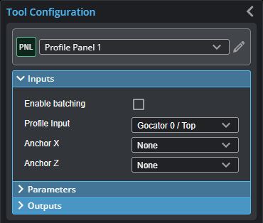
Inputs
|
|
To use a measurement as an anchor, it must be enabled and properly configured in the tool providing the anchor. For more information on anchoring, see Measurement Anchoring. |
| Name | Description |
|---|---|
| Enable Batching |
For more information on arrays, batching, and aggregating, see Arrays, Batching, and Aggregation. |
|
Profile Input |
The data the tool applies measurements to or processes. This tool can optionally take an array as input. If Enable Batching is disabled and the passed array contains more than two elements, GoPxL displays an error. For more information, see Arrays, Batching, and Aggregation. |
|
Anchor X or Anchor Z |
The X or Z measurement of another tool that this tool uses as a positional anchor. Positional anchors are optional. |
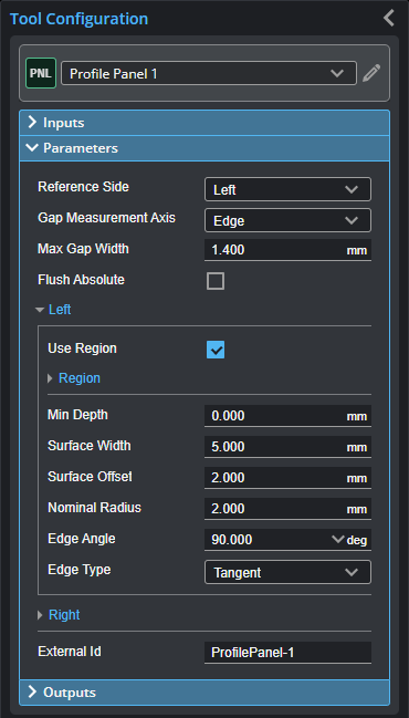
Parameters
You configure the tool's parameters in the expandable Parameters section.
| Parameter | Description |
|---|---|
|
Reference Side |
Defines the side used to calculate the measurement axis (see below) rounded corner. |
|
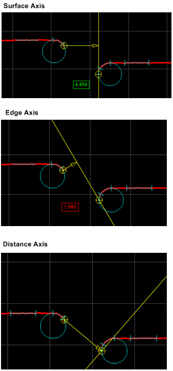
Gap Measurement Axis Gap measurement only |
Defines the direction that the gap is calculated, in relation to the reference side (see above). Surface: In the direction of the fitted surface line of the reference surface. Edge: In the direction perpendicular to the edge of the reference surface. Distance: The Cartesian distance between the two feature locations.
|
|
Max Gap Width |
The maximum width of the gap. Allows the tool to filter gaps greater than the expected width. This can be used to single out the correct gap when there are multiple gaps in the field of view.
|
|
Flush Absolute Flush measurement only |
When enabled, the Flash measurement returns an absolute value instead of a signed value. |
|
External ID |
The external ID of the tool that appears in GoHMI Designer. For more information, see GoHMI and GoHMI Designer. |
| Parameter | Description |
|---|---|
|
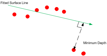
Min Depth |
Defines the minimum depth before an opening can be considered to have a potential edge. The depth is the perpendicular distance from the fitted surface line.
|
|
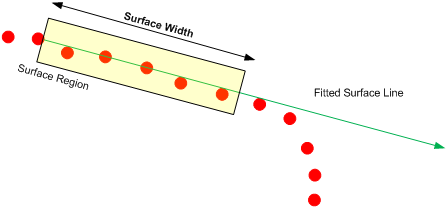
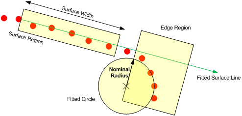
Surface Width |
The width of the surface area in which data is used to form the fitted surface line. This value should be as large as the surface allows. Make sure the surface width does not go beyond the edge of the region of interest (that is, with Region enabled).
|
|
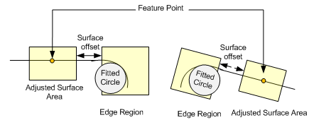
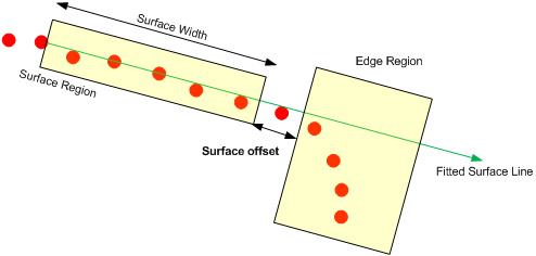
Surface Offset |
The distance between the edge region and the surface region.
Setting a small value allows the edge within a tighter region to be detected. However, the measurement repeatability could be affected if the data from the edge are considered as part of the surface region (or vice versa). A rule of thumb is to set Surface Offset equal to Nominal Radius. Make sure the surface offset does not move the surface width (see above) beyond the end of the region of interest (that is, with Region enabled). |
| Nominal Radius |
The radius of the curve edge that the tool uses to locate the edge region.
|
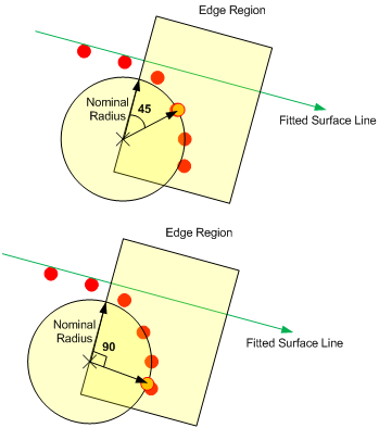
| Edge Angle |
A point on the best fit circle the tools uses to calculate the feature point. The selected point is on the circumference at the specified angle from the start of the edge region.
The angle is measured from the axis perpendicular to the fitted surface line. |
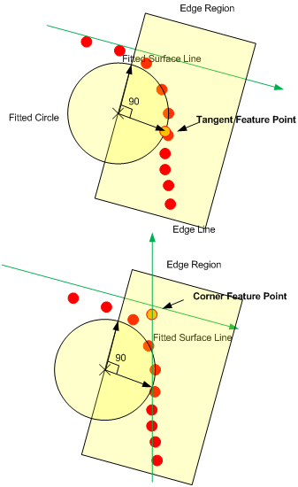
| Edge Type |
Defines the type of feature point to use for the edge (Corner or Tangent).
A tangent edge point is the point selected based on the defined Edge Angle. A corner edge point is the intersect point between the fitted surface line and an edge line formed by interpolating the points at and after the tangent within the edge region. |
Outputs
Most tools provide measurements, geometric features, or data as outputs.
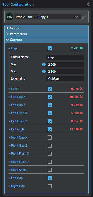
Outputs section with a measurement expanded to show user-configurable decision min/max fields and an external ID
You configure the Min and Max parameters by expanding the measurement in the Outputs section. In order for a measurement to return a Pass decision, the measurement must be between maximum and minimum values; the range is inclusive.
| Measurement | Illustration |
|---|---|
|
Gap Measures the distance between two surfaces. The surface edges can be curved or sharp. |
|
|
Flush Measures the flushness between two surfaces. The surface edges can be curved or sharp. |
|
|
Left Gap X Left Gap Z The X and Z position of the edge feature on the left side used to measure the gap. |
|
|
Left Flush X Left Flush Z Returns the X and Z position of the feature on the left side used to measure flushness. |
|
|
Left Angle Right Angle The angle of the left and right side surface relative to the X axis. |
|
|
Right Gap X Right Gap Z Returns the X and Z position of the edge feature on the right side used to measure the gap. |
|
|
Right Flush X Right Flush Z Returns the X and Z position of the feature on the right side used to measure flushness. |


Gap and Flush Algorithms
The Panel measurement tool uses the same algorithm to find a feature using either the Gap or the Flush measurement. The Round Corner tool uses the same algorithm, but applies it only to the left or the right; you must choose the side in the tool.
This algorithm first searches for two regions on a side: a surface region and an edge region. (See the tables below for the parameters used by the algorithm.)
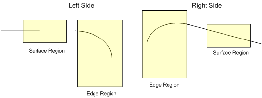
After the algorithm finds the regions, it places a feature point on the surface region based on a set of parameters. You can control the measurement regions, which contain the surface and the edge regions, for the left and the right side. A measurement region also defines the region in which the measurement tool will search for the feature points. Feature points are located on a side using the following algorithm.
-
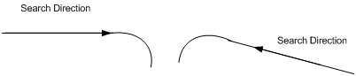
On the left side, search from left to right to find a surface region with data that covers at least the value specified in the Surface Width setting. For the right side, do the same, searching from right to left.
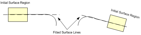
-
If a surface region is found, fit a line, called the surface line, using the data within the area.
-
Search for a valid edge region that is located at least the distance specified in the Surface Offset setting from the end of the surface region. If a surface region is not found, move along the search direction and repeat step 1.
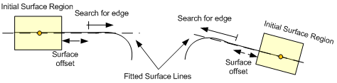
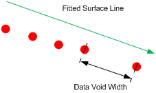
A valid edge region is detected when an edge matches the value in the Nominal Radius setting or when the depth exceeds the value in the Min Depth setting.
-
If a valid edge region is detected, a model fit is applied to the surface and edge regions to accurately determine the region positions and feature point locations. The model fit takes into account the Surface Width, Surface Offset, Edge Angle and the Edge Type parameters.