Profile Roughness
The Profile Roughness tool calculates multiple measurements of profile roughness according to different industry standards, including the following:
ISO 21920
ISO 4287
ASME B46.1
JIS B0601
ISO 13565
ISO 12085
VDA 2006
VDA 2007
Parameters and measurements differ with standards. Choose the standard appropriate for your application.

|
There cannot be a large invalid point range for Profile roughness. Use the region to restrict the valid range in the tool for the calculation. |
|
|
Because the accuracy of a roughness measurement is limited by the X resolution of a sensor, this tool is typically only used on confocal sensors, whose high resolution is better suited for roughness applications. |
For information on adding, managing, and removing tools, as well as detailed descriptions of settings common to most tools, see Tool Configuration.
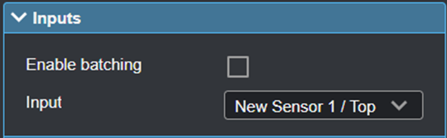
Inputs
You configure the tool's inputs in the expandable Inputs section.
|
|
To use a measurement as an anchor, it must be enabled and properly configured in the tool providing the anchor. For more information on anchoring, see Measurement Anchoring. |
| Name | Description |
|---|---|
| Enable Batching |
For more information on arrays, batching, and aggregating, see Arrays, Batching, and Aggregation. |
|
Profile Input |
The data the tool applies measurements to or processes. |
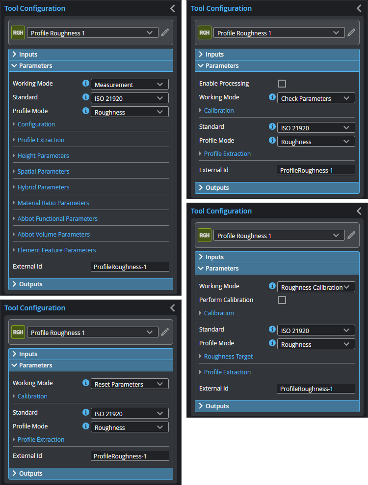
Parameters
You configure the tool's parameters in the expandable Parameters section.
Note that the tool displays different sets of parameters based on what you set Working Mode to.
| Parameter | Description |
|---|---|
|
Enable Processing |
The calculation starts only when this is checked. Only displayed when Working Mode is set to Check Parameters or Roughness Calibration. (Processing happens automatically in other modes.) |
|
Working Mode |
Support the following four working modes:
Before starting the calibration, make sure to remove the old calibration. |
| Perform Calibration |
Performs the calibration. Only displayed when Working Mode is set to Roughness Calibration. |
|
Standard |
The standard the tool uses. Some standards change how options in Evaluation Length behave. For some standards, you should follow the recommendations below.
ISO 21920 Set All Section Lengths and All Sections (no Averaging). These parameters behave the same with this standard.
ISO 4287 Typically, you will set Evaluation Length to "n Section Lengths", and set Section Count to 5. You can also choose "All Section Length" with this standard.
ASME B46.1 Typically, you will set Evaluation Length to "n Section Lengths", and set Section Count to 5. If you use a different Evaluation Length option, note that "All Section Lengths" and "All Sections (no Averaging)" are treated the same with this standard.
JIS B0601 According to the original definition, “All Section Lengths” should be used.
ISO 13565 “Total Profile Length” should be used.
ISO 12085 The same as definitions in ISO 4287, or using “Total Profile Length”.
VDA 2006 “All Section Lengths” and "All Sections (no Averaging)" are the same.
VDA 2007 “Total Profile Length” should be used. |
|
Profile Mode |
In the standards, many parameters are also defined in relation to Primary or Waviness Profile. Select the profile mode after setting a standard. |
|
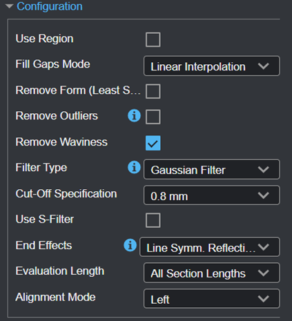
Configuration |
Shows when Working Mode is set to "Measurement". See Configuration for details. |
|
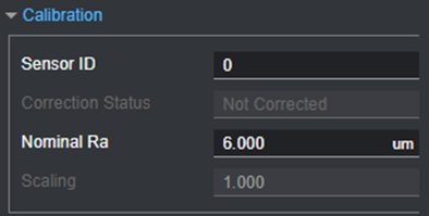
Calibration |
Shows when Working Mode set to any mode other than "Measurement”
|
|
Roughness Target |
Shows when Working Mode is “Roughness Calibration”. The parameters are the same as the Configuration group. |
|
Height Parameters |
Shows different parameters depending on what you select in Standard. See Height Parameters. |
|
Spatial Parameters |
See Spatial Parameters for details. |
|
Hybrid Parameters |
See Hybrid Parameters for details. |
|
Material Ratio Parameters |
See Material Ratio Parameters for details. |
|
Abbot Functional Parameters |
See Abbot Functional Parameters for details. |
|
Abbot Volume Parameters |
See Profile Roughness for details. |
|
Element Feature Parameters |
See Element Feature Parameters for details. |
|
Motif Parameters |
See Motif Parameters for details. |
| Parameter | Description |
|---|---|
|
Use Region Region |
Check to set region size. |
|
Fill Gaps Mode |
Choose Linear Interpolation to fill gaps in the profile but keep the profile as natural as possible. |
|
Remove Form (Least Squares) |
When checked, displays a drop-down containing one of the following:
|
|
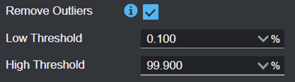
Remove Outliers |
Check to remove outliers from the profile and set Low Threshold and High Threshold. The outliers are defined according to the Sigma Rule in terms of the given percentage multiplied by 1.5.
|
|
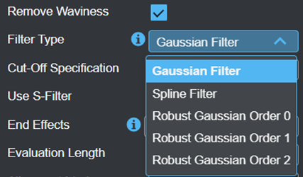
Remove Waviness |
Check to remove the waviness of the profile. Select the filter in Filter Type.
The tool provides the following filters according to the ISO 16610 standards series, which allow different filter kernels having different shapes. Choose the filter depending on your application and its sensitivity to the curvature of the waviness.
Gaussian Filter: According to ISO 16610-21, ISO 16610-28 If selected, set choose the appropriate option in End Effects (see End Effects).
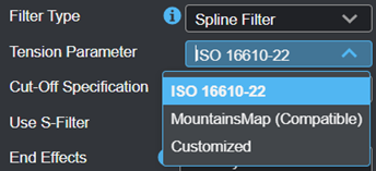
Spline Filter: According to ISO 16610-22, ISO 16610-28. If selected, set Tension Parameter to control how tightly the spline curve fits through the data points.
Robust Gaussian Order 0: According to ISO 16610-31, ISO 16610-28. Using Savitzky-Golay filter coefficients:
Retaining the zeros moment means to reduce end effects.
Robust Gaussian Order 1: According to ISO 16610-31, ISO 16610-28. Using Savitzky-Golay filter coefficients:
Retaining the first moment means to reduce end effects.
Robust Gaussian Order 2: According to ISO 16610-31, ISO 16610-28. Using Savitzky-Golay filter coefficients
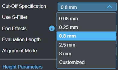
The cut-off is selected depending on the workpiece surface either according to the valley spacing, or the expected roughness values. At the same time the total evaluation length and the corresponding total profile length are defined according to standards. Deviations are necessary if the workpiece does not allow the required total profile length. If the actual possible total profile length on the workpiece surface is not enough for lt, the number of sampling lengths is reduced accordingly and specified in the drawing. If the actual available total profile length is less than a sampling length, the total height of profile Pt of the primary profile is evaluated instead of Rt or Rz. |
|
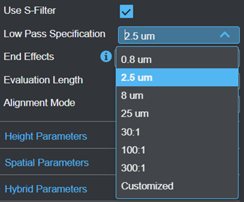
Use S-Filter |
Check to use a low pass filter with the cut-off wavelength defined in Low Pass Specification.
|
|
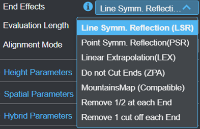
Shows when Remove Waviness is checked. The end effect is the unintended changes in filtration response in the both end sections of an open profile, and the end effect correction methods are according to standard ISO 16610-28.
Line Symm. Reflection (LSR) A measured profile is extended by horizontal reflection on the left hand and right hand, respectively.
Point Symm. Reflection (PSR) A measured profile is extended by horizontal reflection in conjunction with vertical reflection on the left and right hand respectively. Both reflection lines shall intersect at the respective end point of the profile.
Linear Extrapolation (LEX) In the case of linear extrapolation, a least-squares line is fitted to the profile within the left and right end effect regions.
Do not Cut Ends (ZPA) Zero padding is a simple method for retaining the total length after filtering the profile. Profile z(x) is padded with zeros over the total length.
MountainsMap (Compatible) Tries to make filtering compatible with MMP "Manage End Effect". This setting only applies to Guassian filters.
Remove 1/2 at each end No end effects treatment required as the critical regions are not involved in the calculation.
Remove 1 cut off each end No end effects treatment required as the critical regions are not involved in the calculation. |
|
|
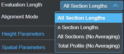
Evaluation Length |
The evaluation length. One of the following:
All Section Lengths The maximum available sections will be used.
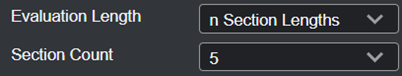
n section lengths Set the number of sections in Section Count. The effective section number is always limited by the available length.
All Sections (no Averaging) All parameters as long as the definition allows are calculated in the entire evaluation length.
Total Profile (no averaging) All parameters as long as the definition allows are calculated in the total profile length. |
|
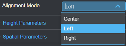
Alignment Mode |
Note: The alignment in MountainsMap is left-justified. |


The principle of the Motif standard consists of looking for local peaks and valleys in the primary profile, and associating one valley with the closest preceding and following peaks in order to create a Motif. Several iterative combinations of two Motifs each assure that the most important Motifs, the width of which fall below the limit A, are considered. If not otherwise specified, the default value is A = 0.5 mm. The limit A has a similar function as the cut-off in the Gaussian filtering.
Outputs
Most tools provide measurements, geometric features, or data as outputs.
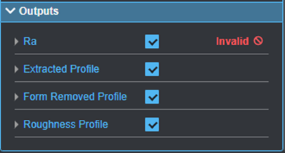
You configure the Min and Max parameters by expanding the measurement in the Outputs section. In order for a measurement to return a Pass decision, the measurement must be between maximum and minimum values; the range is inclusive.
| Measurement |
|---|
|
Ra Arithmetic average of the absolute values of the roughness profile ordinates. For the other measurements, see the parameter details above. |
| Type | Description |
|---|---|
| Extracted Profile |
Extraction of the measured profile with the defined region. |
| Form Removed Profile | Obtained after removal of the nominal form (F-operation). |
| Roughness Profile | Obtained after filtering including a (high-pass) L-filter (λc) rejecting long wavelengths. When presenting the roughness profile, the mean line is the zero line. |