Wide Layouts (Surface Align Wide Tool)
The Surface Align Wide tool performs a high-accuracy alignment of multi-sensor laser line profiler systems in wide layouts (side-by-side). The tool is only intended for use with these sensors and system layouts.
Before using this tool, you must fabricate a special pyramid plate alignment target (for more information, see Alignment Target and Setup), and then scan this target, recording the data for the alignment procedure with this tool.

|
Performing alignment using the Surface Align Ring or Surface Align Wide tools (which results in 6 degrees of freedom) involves considerable setup effort. First, the 6 DoF alignment targets are more difficult to manufacture than an alignment bar and require a very high degree of accuracy; 3D printed alignment targets are not usually sufficiently accurate. Second, the alignment tools have many parameters that must be properly configured to successfully perform an alignment. |
Unlike alignment using the Alignment panel on the Scan page, the Surface Align Wide determines the X angle rotation, giving you a full six degrees of freedom (for information on coordinate systems, see Profile Output). This method of alignment will produce higher accuracy scans, and allows for higher scan rates, due to the use of a different data-merging algorithm.
|
|
This tool requires acceleration (either by a PC-based application or by GoMax). For more information, see Running GoPxL on a Windows PC. |
|
|
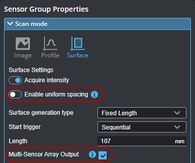
Before scanning the alignment target, remember to uncheck Enable uniform spacing in the Scan mode section on the Scan page. Also enable Multi-Sensor Array Output.
|

|
Sensors must not previously have been aligned using the alignment routine on the System > Alignment page. This is indicated by "Not Aligned" on that page. If necessary, click Clear Alignment.
|
After configuring the alignment tool (see the parameters below), you must check the Enable Processing checkbox to start processing of the alignment target scan data. After the tool has finished processing the data and has successfully aligned the sensors, it produces the XML file you load into a Surface Merge Wide tool, as well as a Difference Surface data output that you can use to assess the quality of the alignment. (The tool actually creates two copies of the initialization file: one called Configuration.xml, and another with a date-time stamp in its name.)
During processing, the tool segments the planes and then performs a best fit of the scanned target to the nominal dimensions you provide in the tool. For this reason, an accurately manufactured alignment target, correct nominal dimensions, and scan data that only includes the target are crucial to success. For more requirements and guidelines, see Alignment Target and Setup.
To determine whether the alignment succeeds and to assess the quality of the alignment, you use the Standard Deviation measurement output and the Difference Surface output.
If the Standard Deviation measurement returns Invalid, the alignment has failed. If Standard Deviation returns a numerical value, it represents the "uncertainty" of the alignment process (basically, a numerical assessment of the quality of the alignment). This value should be close to zero.
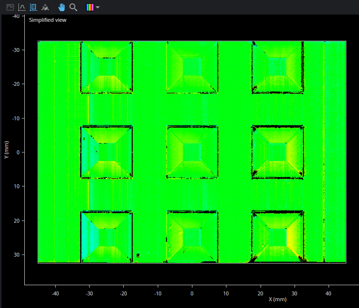
The Difference Surface output represents discrepancies between the expected, nominal values provided in the tool (the dimensions of the alignment target, as well as the number and positions of the sensors) and the scan of the alignment target. In a "good" Difference Surface output, most of the data points should be relatively close to zero, for example on the left below. (The image on the right is a full, merged scan of the target produced by Surface Merge Wide, to give context.)
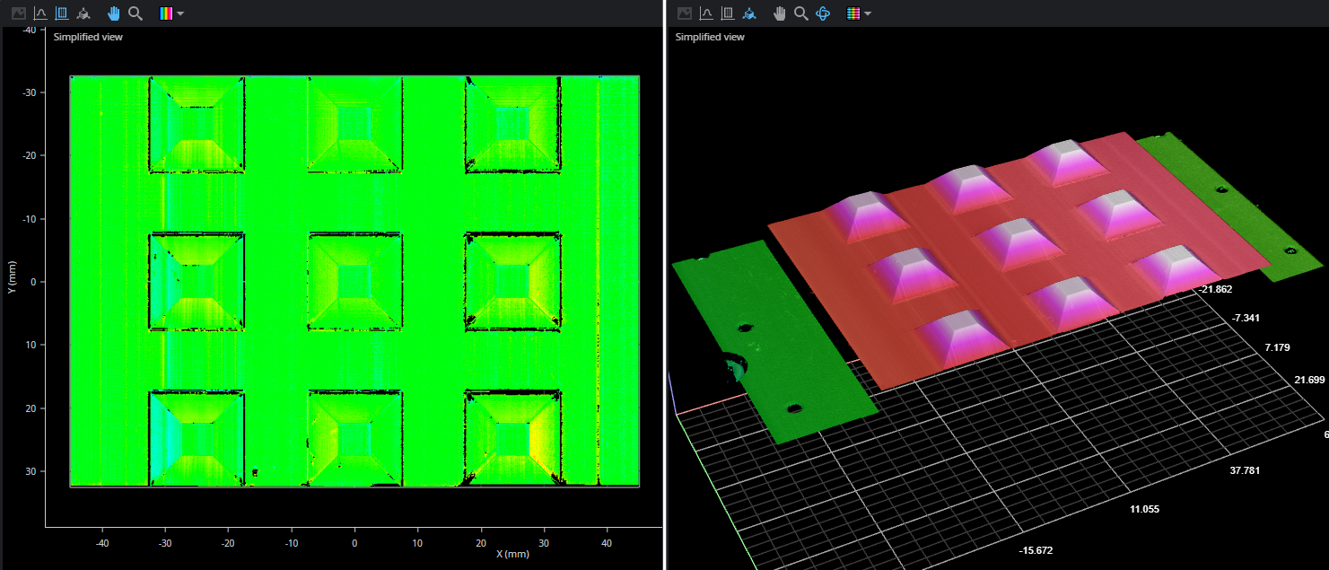
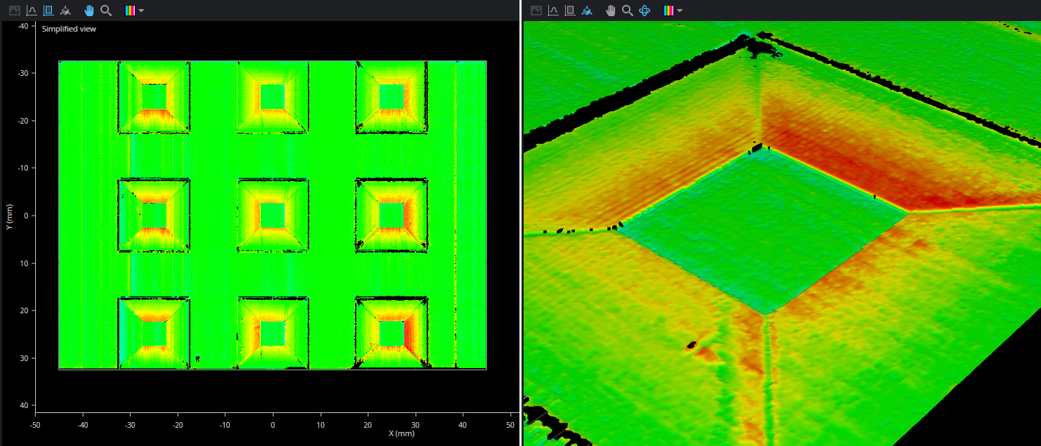
Discrepancies are indicated as height differences above or below zero, that is, how "different" the nominal values and the actual scan data are. In the following images, a discrepancy of -0.15 between the target's top width and the scan data shows up as a "ring" around the top of the pyramid.
For more information on how to interpret the Difference Surface, see Understanding the Difference Surface.
It's important to remember that in order to perform scans and measurements in production using a system aligned using this tool, you must include a Surface Merge Wide tool (see Surface Merge Wide) in your scanning job's tool chain, and load the XML initialization file created by this tool into the merging tool: The merging tool uses the transformations in the initialization file to combine the scans from the individual sensors into single frames of Surface scan data. You can then apply any built-in tools to the processed data that Surface Merge Wide produces; for information on the tools, see Tools - Measurement and Processing.

Note that after aligning using this tool, on the Alignment panel on the Scan page, GoPxL indicates that the sensors are unaligned. This is normal.
Alignment Target and Setup
This Surface Align Wide tool requires the use of a pyramid plate alignment target, which consists of rows and columns of truncated pyramid forms. You can find CAD files for an example 3x3 pyramid target under Tools\Alignment CAD\Pyramid Plate in the Utilities package (e.g., 14405-x.x.xx.xx_SOFTWARE_GO_Utilities.zip, available on LMI's Product Downloads page). Note that you must adapt the size of the plate and the pyramids to the field of view (FOV) of the sensors in your system: generally speaking, the plate should be scaled so that a truncated pyramid fills most of a sensor's FOV. For details, see the list of requirements below. For definitions of the dimensions of the target as used in the tool, see Pyramid Plate Target Parameters.
|
|
The alignment target LMI provides in a CAD file is appropriate for sensors angled up to roughly 15° from vertical. For information on alignment target requirements, see below. |

A 3x3 pyramid plate. Exact dimensions of the plate
and the pyramids will depend on the sensors in your system.
The following target requirements must be satisfied for best results:
-
3D printed targets are not recommended, as they may lack the required accuracy. Ideally, you should machine the alignment target.
-
Scale the target so that each sensor covers the area of only one column. However, if an application requires that sensors must be angled so that their laser planes mostly overlap, two sensors can see the same column.
-
Maximize the target size to ensure that as much of the base area is visible to the sensor. Keep in mind however that the target size should be smaller than the combined FOV.
-
Make sure the alignment target surface is not too shiny or too dark to be scanned. A diffuse surface is best.
-
Edges do not need to be perfectly sharp: The alignment tool performs a plane fit to points within the planar surfaces of the target and excludes data close to the edges.
-
Pyramid heights should be at least 1/5 of the measurement range of the sensor. For example, the measurement range of a Gocator 2520 is 25 mm; for this type of sensor, the pyramid height should be at least 5 mm. (For measurement range specifications, see Sensors.)
-
Pyramid tops should be at least 1/10 of the sensor's FOV, taking into account the location of the target along the Z axis in the sensor's measurement range. For example, at the midpoint in the measurement range of a Gocator 2520, the FOV is 28.75 mm; for this type of sensor, the pyramid tops should be at least 2.875 mm along each side.
-
The pyramid angle (the angle between the side planes and the base plane) must be greater than 30°.
-
There should be no holes in the flat area between sensors.
-
Only one row of pyramids is required for the alignment procedure, but using additional rows improves the accuracy of the alignment.
When mounting sensors over the alignment target and configuring the active area, keep the following in mind:
-
Pyramids should be roughly centered in the FOV of each sensor.
-
For best results, all four sides of a pyramid should be visible to a sensor.
-
Given the size of the top widths of the pyramids and the distance of the sensors to the alignment target, the top widths should be represented by a minimum of 100 to 200 data points along the X axis in the scan data.
-
The flat area between the pyramids must be visible to the sensors.
-
Pyramid sides should not be angled from a sensor's Z axis by more than 60 degrees. So for example, if you use an alignment target with 45° pyramid sides, a sensor's Z axis shouldn't be angled by much more than 15 degrees from vertical. And for sensors angled 30 degrees from vertical, for example, an alignment target whose pyramid sides are angled only 30 degrees would be more appropriate
-
Block any unwanted planar data during scanning, such as the conveyer belt beneath the target. To do this, you can shrink the sensor’s active area in the Acquire > Scan page to exclude this data while scanning the target. Remember to reset the active area after the alignment. For more information on setting the active area, see Active Area.
After you have scanned the alignment target, verify in the scan data that each of the five planar segments of each pyramid (the top and the four sides) is represented by at least 100 x 100 data points. If the point count along the X axis is less than 100, one alternative way is to scan the target in a smaller Y Spacing to meet the 100 x 100 points per segment threshold.
Alignment Procedure
The following provides the steps involved in performing a high-accuracy, tool-based alignment.
|
|
The following assumes you are scanning the alignment target using unaccelerated sensors and then uploading the recording to a PC instance of GoPxL. The procedure for doing this with accelerated sensors is similar. |
To perform the alignment:
| 1. | Fabricate an alignment target appropriate for your system (wide layout versus ring layout). |
For details on the alignment target, see Alignment Target and Setup.
| 2. | If you have not already done so, set up and configure the multi-sensor system. |
The following sections describe installing, setting up, and configuring a system:
Sensor Management and Maintenance
Scan - Configuring Acquisition
| 3. | Make sure to do the following. |
Disable Uniform Spacing and enable Multi-Sensor Array Output in the Scan mode section on the Inspect > Scan page.
Sensors must not previously have been aligned using the alignment routine on the System > Alignment page. This is indicated by "Not Aligned" on that page. If you see "Aligned" here, click Clear Alignment,

|
|
Although you can scan the alignment target without acceleration, you must perform the alignment using PC-based acceleration (for more information, see Running GoPxL on a Windows PC). Because starting acceleration after having performed a scan clears scan data from a sensor, if you are going to perform alignment on-sensor, you should start acceleration before continuing. You can also optionally download the scan data and perform the alignment on the scanned target using GoPxL on Windows. For more information, see Working with Scan Data (Toolbar). |
| 4. | If any sensors are installed in a "reversed" orientation (that is, such that the conveyor moves in the same direction as the sensor's positive Y axis), be sure to set the sensor's layout to Reverse. |
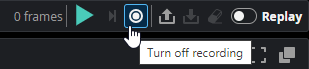
| 5. | Enable recording by clicking the Record button to the right above the data viewer. |
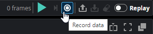
GoPxL shows recording is enabled.

| 6. | Start the transport system and then perform a scan of the alignment target. |
| 7. | Turn off recording. |
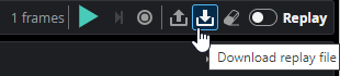
| 8. | Download the recording and make note of the downloaded file's location. |
| 9. | Launch a PC instance of GoPxL. |
For more information, see Running GoPxL on a Windows PC.
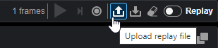
| 10. | Upload the recording of the alignment target in the PC instance. |
| 11. | On the Inspect > Tools page, add a Surface Align Wide tool. |
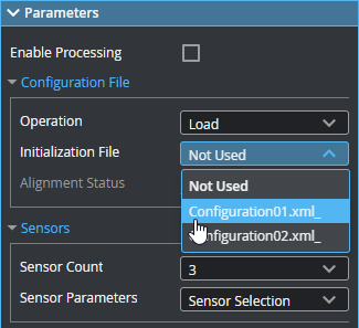
| 12. | (Optional) If you have a previously saved configuration file, expand the Configuration File section and choose Load from the Operation drop-down, load that file, and go to step 16. |
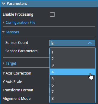
| 13. | In the expandable Sensors section, set Sensor Count to the number of sensors in the system. |
| 14. | Under Sensor Parameters, select the sensors, one by one, and configure the parameters related to the sensor's position. |
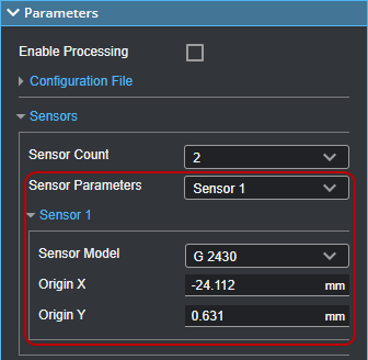
For more information, see Sensor Parameters.
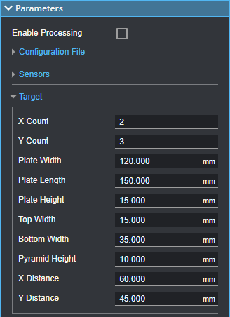
| 15. | Expand the Target section and configure the parameters related to the alignment target. |
|
|
It is crucial to set these values correctly. These nominal values must also be accurate with respect to the alignment target. |
For more information, see Pyramid Plate Target Parameters.
| 16. | Configure the tool's remaining parameters (see Parameters). |
| 17. | Enable any measurements or the Processed Surface outputs if needed. |
These outputs can be useful for diagnostics.
| 18. | Check the Enable Processing checkbox. |
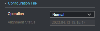
The tool processes the scan data, using the provided sensor positions or rotations and alignment target characteristics, and saves a configuration file to C:/GoTools/SurfaceAlign. If the alignment process succeeds, the Alignment Status field in the Configuration File section displays the time and date of the alignment.
You must load the resulting configuration file in a Surface Merge Wide tool, typically in a separate job, which transforms and merges the multi-sensor scan data into a common coordinate system. You can then apply other measurement tools to the merged scan data. For more information on the merging tool, see Surface Merge Wide.
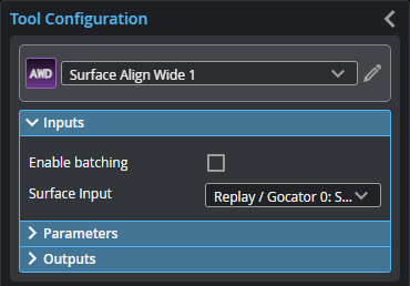
Inputs
You configure the tool's inputs in the expandable Inputs section.
| Name | Description |
|---|---|
| Enable Batching |
Leave this setting unchecked. |
|
Surface Input |
The data the tool applies measurements to or processes. If the scan data in Surface Input uses uniform spacing (that is, you scanned the target with Enable uniform spacing checked), the tool displays additional sensor parameters that you must set. For more information, see Using Uniform Spacing During the Alignment. |
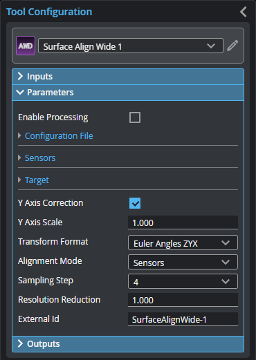
Parameters
You configure the tool's parameters in the expandable Parameters section.
| Parameter | Description |
|---|---|
|
Enable Processing |
Causes the tool to perform the alignment. If the alignment is successful, the tool creates an XML alignment (calibration) file containing the transformations of the sensors that you must use with the Surface Merge Wide tool when scanning production targets to merge scan data. Make note of the XML file indicated in the log pane for use with Surface Merge Wide. Make sure to properly configure the tool before enabling this option. Disable it after performing the alignment; otherwise, the tool will continue performing the alignment on new frames of data, which will have an impact on performance. |
| Configuration File | An expandable section that contains configuration file-related parameters. |
|
Operation |
Actions that apply to the tool's configuration files. One of the following:
|
| Sensors | An expandable section that contains sensor-related parameters. |
|
Sensor Count |
Indicates the number of sensors in the system. |
|
Sensor Parameters |
A drop-down that displays the settings of the selected sensor. For descriptions of the individual sensor parameters used for the alignment, see Sensor Parameters. |
|
Target |
An expandable section that contains parameters related to the pyramid plate target's specifications. For descriptions of the pyramid plate parameters, see Pyramid Plate Target Parameters. For information on alignment targets, see Alignment Target and Setup. |
| Y Axis Correction |
Compensates for errors in encoder settings, which can distort scan data. If you cannot change the encoder settings or if you are working with data recorded with an incorrectly configured encoder, enable this setting. The tool will adjust the Y scaling to compensate and display the value in Y Axis Scale. |
| Y Axis Scale |
The Y axis scale the tool calculates to compensate for incorrect encoder settings. Only displayed when Y Axis Correction is enabled. |
|
Transform Format |
The transformation format the tool uses. Typically, you can leave this at its default setting. Choosing a different format may be useful if you need to compare what the sensors detect to the transformation format used in your CAD package, for example. The setting does not affect alignment. One of the following:
|
|
Alignment Mode |
The coordinate system used in the aligned system. One of the following: Sensors The Y axis is in the direction of motion. The resulting Y rotation of sensors is such that the average Y rotation is 0. X, Y, and Z = 0 are at average sensor center Target Y Angle The resulting Y rotation of sensors is such that the target surface is aligned to be horizontal. This mode is recommended when aligning to a conveyor on which the target is placed flat. X, Y, and Z = 0 are at average sensor center. |
|
Sampling Step |
The step in data points in both directions with which the surface is processed. Choosing a higher sampling step reduces the processing time the tool requires, but reduces fit accuracy. Useful if the surface being processed has a large number of data points. Typically, you will want to use as low a sampling step as possible; use a high sampling step only for initial testing purposes. |
|
Resolution Reduction |
Reduces the lateral resolution of the heightmap to reduce processing time. |
|
External ID |
The external ID of the tool that appears in GoHMI Designer. For more information, see GoHMI and GoHMI Designer. |
Setting Origin X and Origin Y
The following settings are available in the expandable Sensor {n} sections when Sensors > Sensor Parameters is set to one of the sensors in the system.
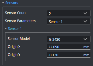
The Origin X {n} and Origin Y {n} settings in the Surface Align Wide tool represent the estimated, real-world, X and Y position of the intersection of a sensor's Z axis with the flat surface of the pyramid plate, relative to the center of a bounding box that encompasses the intersections of all sensors in the system.
For example, in the following example of a two-sensor system, with the sensors placed side by side (no displacement along the Y axis), the X position of the intersection of the left sensor's Z axis and the alignment target's flat surface is roughly -25 mm, and the X position for the right sensor is 25 mm. You would use these values in the Origin X parameters of the appropriate sensor.

In the following, a three-sensor system with sensors positioned at different Y locations (viewed from above), the Origin X and the Origin Y value of each sensor is set to the distance (X and Y position) of the intersections between the alignment target surface and the sensors' Z axes, relative to the center of the bounding box that encompasses the intersections.

Note however that for sensor systems with sensors positioned at different Y locations, you can set Origin Y to 0 if the entire alignment target is scanned during the alignment procedure: the algorithm uses the edges of the alignment target to determine the Y component of the sensors' origin. If you do not scan the entire alignment target during the procedure, you must enter an estimate of the Y position of the sensors' origins.
|
|
It is very important to consult the specifications of the sensors in your system to determine the direction of X and Y. In multi-sensor systems, the Y axis is determined by the Main sensor's orientation. |
If your application requires that sensors should be angled, remember to take this into account when estimating the values needed for Origin X and the Origin Y, paying attention to where the Z axis of each sensor intersects with the alignment target's lower flat surface.
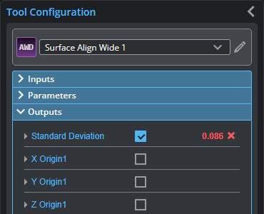
Outputs
Most tools provide measurements, geometric features, or data as outputs.
| Measurement |
|---|
|
Standard Deviation Alignment uncertainty (an indicator of alignment quality). Returns Invalid if the uncertainty is very high. |
|
X Origin{n} Y Origin{n} Z Origin{n} The X, Y, and Z transformations calculated for sensor {n}. |
|
X Angle {n} Y Angle {n} Z Angle {n} The X, Y, and Z angle transformations calculated for sensor {n}. |
| Type | Description |
|---|---|
|
Difference Surface |
A heightmap that displays discrepancies and agreement between the nominal values provided in the tool's parameters and the actual dimensions in the scan data. Use this output to assess the quality of the alignment and to determine where there may be issues. For more information, see See Wide Layouts (Surface Align Wide Tool). |
Understanding the Difference Surface
The Difference Surface output is a heightmap that displays discrepancies and agreement between the alignment target dimensions provided in the tool's parameters (the expected dimensions) and the actual dimensions of the target in the scan data. The tool displays areas where the scan data is consistent with the nominal values as close to Z = 0. In areas where the scan data is higher than expected, the tool displays data points with a higher Z value (that is, significantly greater than 0). Where the scan data is lower than expected, the tool displays data points with a lower Z value (that is, significantly less than 0).
A "good" Difference Surface is nearly flat, indicating that the majority of the data points are close to the expected dimensions of the target. The scan data should also contain the entire alignment target, including the area between the pyramids.
The presence of relatively systematic differences (for example, around the tops or the bases of all of the pyramids) can result from incorrectly entered values in the tool's Target parameters, or an incorrectly manufactured alignment target (for example, using incorrect specifications). To properly assess whether there are discrepancies, you may need to zoom in on the scan data in the data viewer. It may also help to adjust the way the colors of the height map are displayed using Region or Manual in the Range setting above the data viewer.
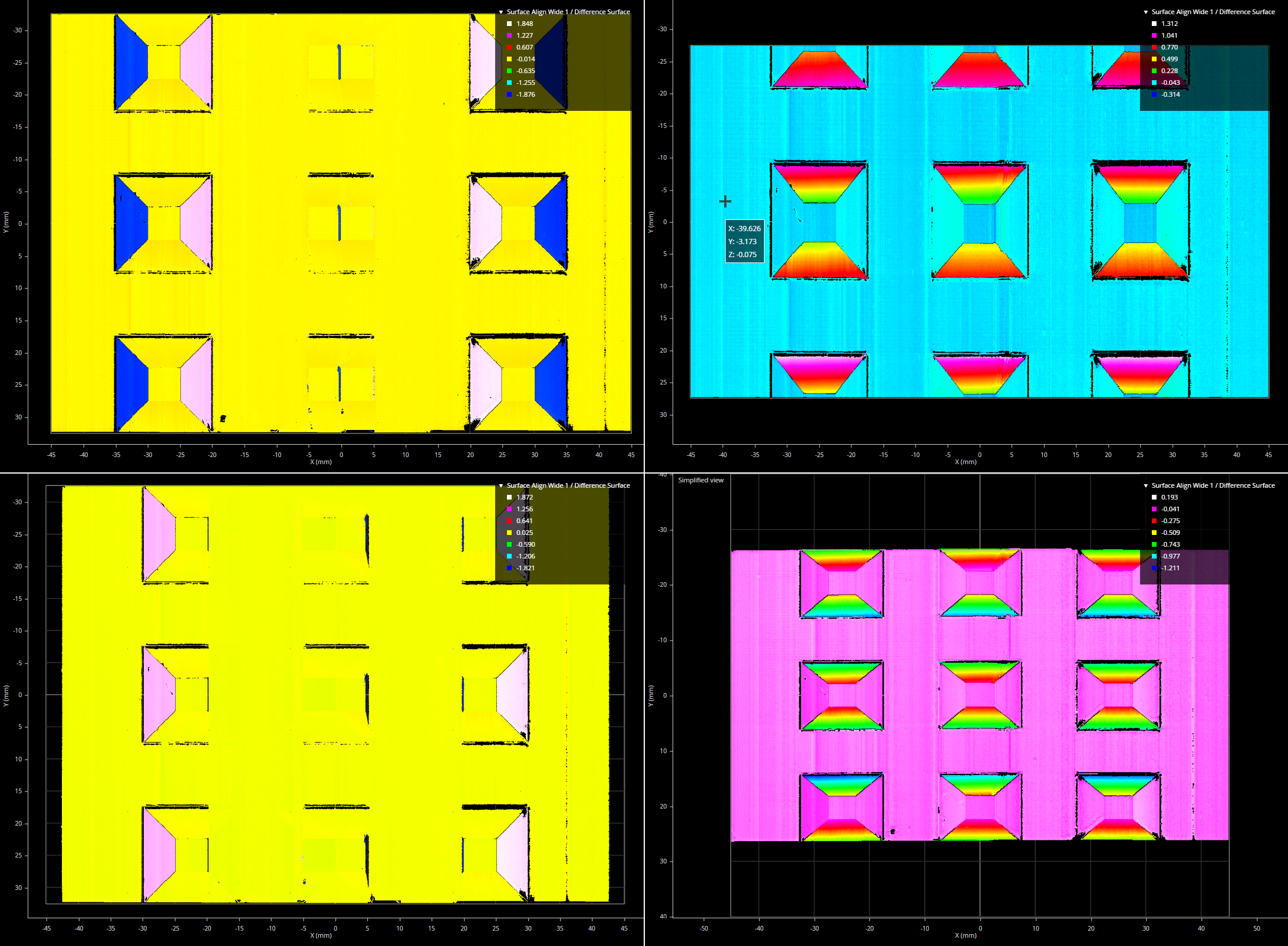
For example in the following, from left to right, the values provided in the Top Width, Bottom Width, and Pyramid Height parameters are roughly 6% lower than the actual dimensions of the alignment target. The height deviations shown in the Difference Surface output are "focused" around the area that is problematic.
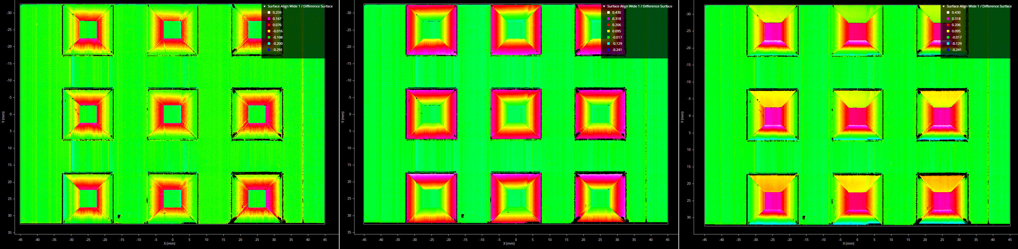
In the following, the same pyramid parameters are set roughly 9% higher than the actual dimensions. The resulting Difference Surface represents these discrepancies as being lower than expected in the heightmap.
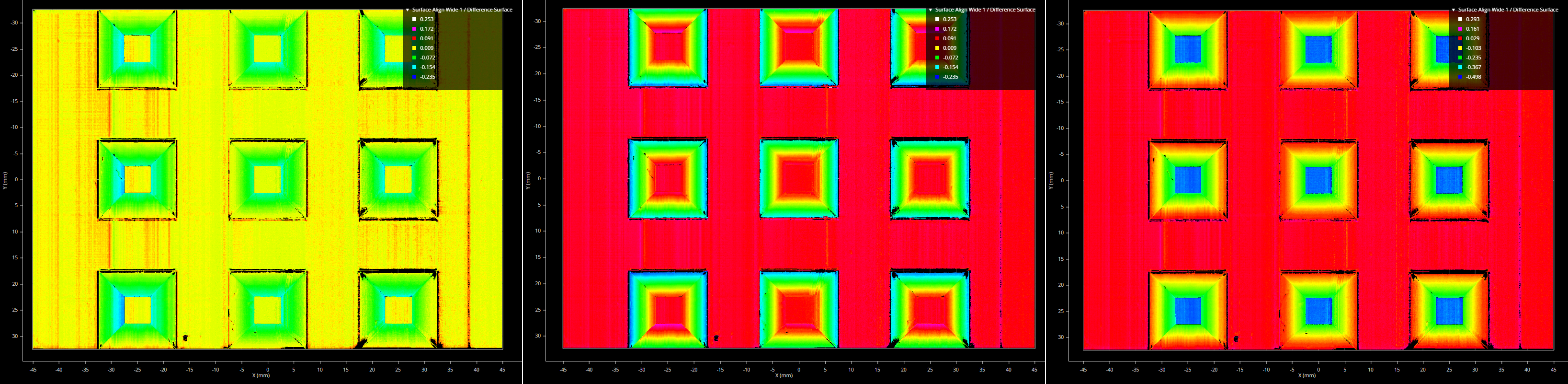
Similarly, relatively systematic deviations along a specific axis can indicate discrepancies between the values provided in X Distance or Y Distance and the actual target as scanned. In the following Difference Surface outputs, there is a nominal-actual discrepancy along the X axis and Y axis, respectively.
More extreme discrepancies can produce more obvious distortions in Difference Surface. In the following images, on the left, the pyramid tops of the center column are almost missing, resulting from X Distance being above and below nominal, respectively. On the right, the pyramids are stretched or compressed along the Y axis, resulting from Y Distance being above and below nominal, respectively; the target is also cropped.
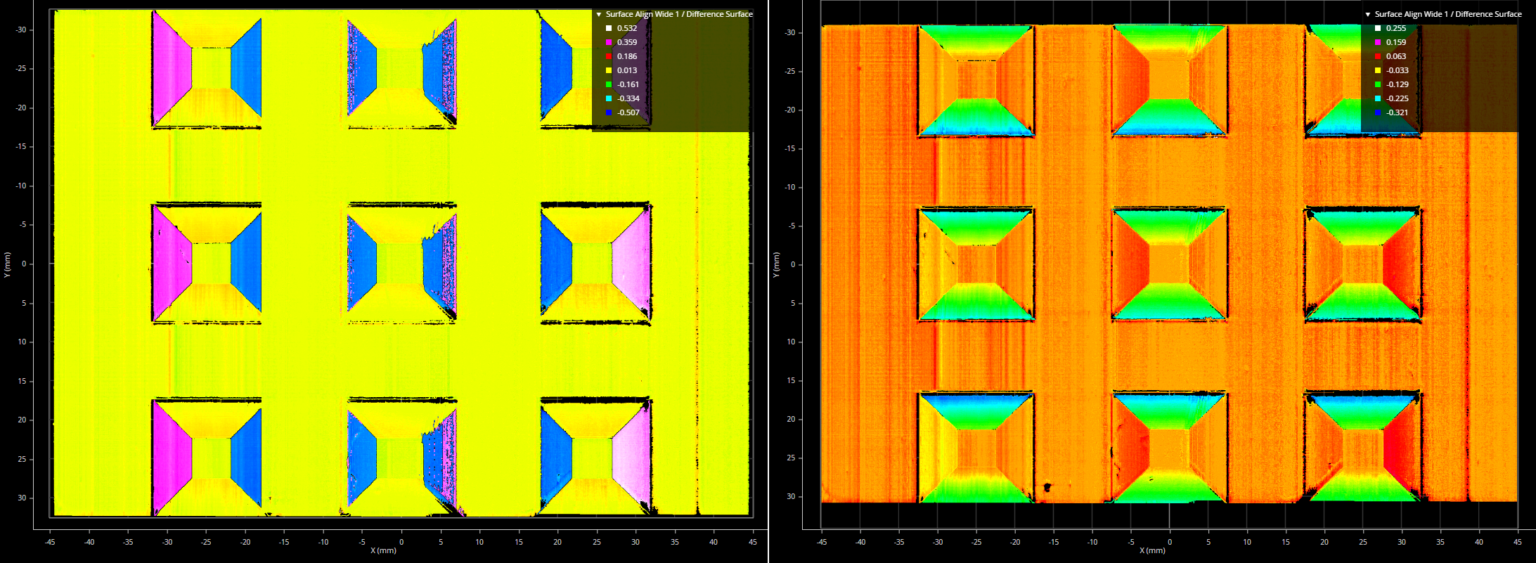
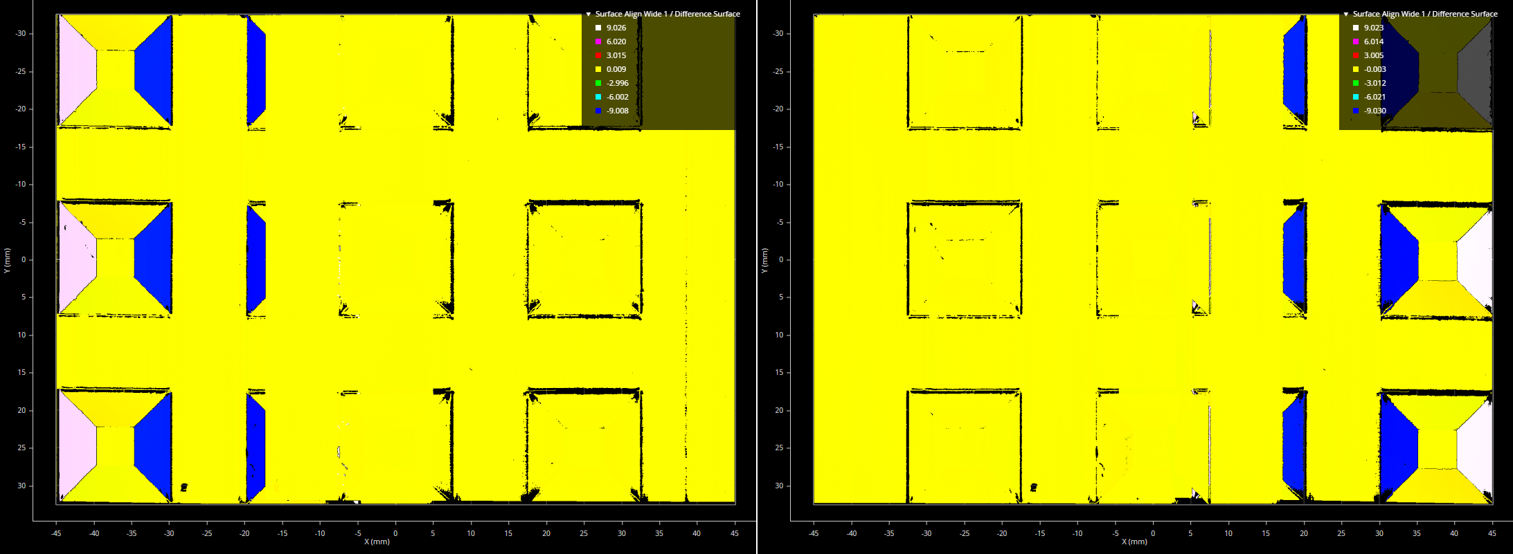
An incorrectly set Origin X or Origin Y parameter, in the Sensors section, can result in somewhat systematic discrepancies. In the following images, the X Origin of the left and the right sensor, respectively, is incorrectly set. Note that the values used are extreme.
Note that the pyramid plate parameters, in the Target section, do not affect the alignment. These parameters only affect the size of the Difference Surface output.
Using Uniform Spacing During the Alignment
If you choose to enable Uniform Spacing when scanning the alignment target, you must perform these additional steps when running the alignment tool on the scanned target. Otherwise, the alignment will fail.
These steps separate the individual sensors' scan data in the heightmap so that the alignment tool can process the scan data from each sensor individually. To do this, you set artificial offsets along the X axis to separate the scan data so that there is no overlap between the sensors.
Do the following:
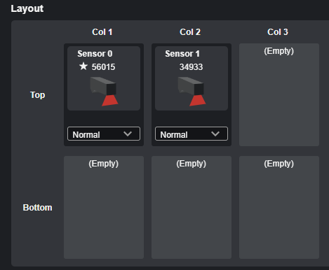
| 1. | (Optional) In the web interface, go to the System > Design page, click the action menu icon, click Add and manage sensors, and make note of the names, serial numbers, and positions of the sensors listed in the Layout section. |
This information can be useful when you continue configuring the system in other parts of the web interface.
| 2. | In the web interface, go to the Scan page. |
| 3. | For each sensor in the system, in the Active Area tab, make note of the values for X Field of View and the Min value in the X center row. |
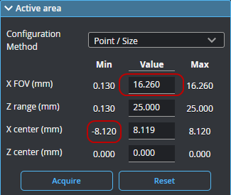
| 4. | For each sensor in the system, in the Transform section, set X Offset to a value that eliminates any overlap between sensors, and make note of this value. |
For example, for sensors with a 100 mm field of view, you might choose 1 or 2 mm for a blank area. Therefore, for the first sensor, you could set its X Offset 0 mm.
For the Right sensor, you could set its X Offset to 101 or 102 mm.
For systems with more than two sensors, set the offsets in a similar way to ensure that the individual sensors' scan data in the heightmap does not overlap.
| 5. | If you haven't already done so, go to the Scan > Tools page and add an instance of Surface Align Wide. |
| 6. | For each sensor, select the sensor you need to configure in the Sensors > Sensor Parameters drop-down and copy the "X Field of View," "X Start (Min value)," and "X Offset" values from the Scan page into the corresponding parameters in the alignment tool. |
Make sure to do this for each sensor.
| 7. | If you have not already done so, finish configuring the rest of the tool's parameters. |
Note that the artificial offsets you use to create the combined heightmap for the alignment procedure are unrelated to the values you need to use in Origin X {n}; for more information on this setting, see Setting Origin X and Origin Y.