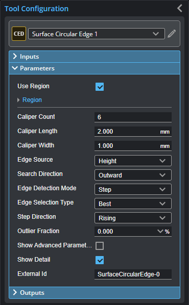
Surface Circular Edge
The Circular Edge tool fits a circle to a circular edge in the scan data, using either height map or intensity data. The edge can be the outer edge of a disc-like feature or the inner edge of a hole. The tool can optionally work with partial data, as little as 1/4 of a circle, letting it work with rounded corners.
The tool lets you measure the position and radius of the circular feature and determine its roundness error. The feature is expected to be relatively round and not, for example, ovoid.
The tool also returns minimum and maximum error points to either side of the circle and gives the error distance measurement of minimum/ maximum points to the circle.
The tool uses one of four standard methods to calculate roundness. The choice of method affects the other measurements.
- Least Square Circle (LSC)
- Minimum Zone Circle (MZC)
- Maximum Inscribed Circle (MIC)
- Minimum Circumscribed Circle (MCC)
The tool can also generate circle and center point geometric features that Feature tools can take as input for measurement. For more information on Feature tools, see Feature Measurement.
Some of the tool parameters are hidden unless Show Advanced Parameters is checked.
For information on adding, managing, and removing tools, as well as detailed descriptions of settings common to most tools, see Tool Configuration.
Calipers, Extracted Paths, and Edge Points
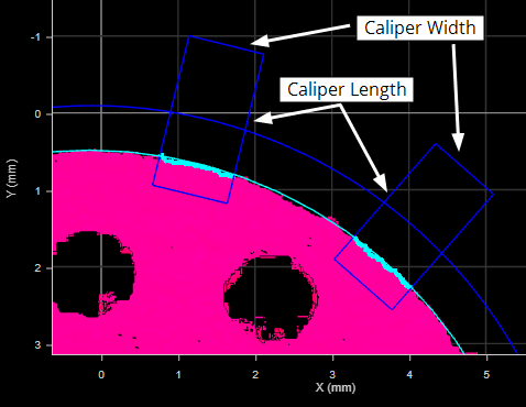
To fit a circle to the scan data, the Surface Circular Edge tool starts by overlaying evenly spaced calipers along a circular path constrained by the region of interest.

Rectangular calipers (dark blue) placed along circular path (dark blue), constrained by the region
The circular path can optionally be partial, and starts at a defined orientation around the Z axis. The circular path can be as short as 1/4 of a circle, letting it work with rounded corners. Calipers extend vertically to fill the entire region of interest.
Internally, the tool extracts profiles from the data within each caliper, running from the end of the caliper closest to the center of the tool's region of interest to the end farthest from the center. The tool then searches for steps in each profile that meet the criteria set by the tool’s settings, such as minimum height, direction (whether it is rising or falling), and so on.
The tool places an edge point on each selected step. The tool then uses the edge points in all the calipers to fit a circle. The various characteristics of the fitted circle are then returned as measurements.
Inputs
You configure the tool's inputs in the expandable Inputs section.


|
To use a measurement as an anchor, it must be enabled and properly configured in the tool providing the anchor. For more information on anchoring, see Measurement Anchoring. |
| Name | Description |
|---|---|
| Enable Batching |
For more information on arrays, batching, and aggregating, see Arrays, Batching, and Aggregation. |
|
Surface Input |
The data the tool applies measurements to or processes. |
|
Anchor X Anchor Y Anchor Z |
The X, Y, or Z measurement of another tool that this tool uses as a positional anchor. Positional anchors are optional. |
| Anchor Z Angle |
The Z Angle measurement of another tool to use as a rotational anchor for this tool. Rotational anchors are optional. |
| Reference Plane | Uses the feature output of a Surface Plane tool as a reference plane. Useful to correct the scan data if the target is slightly tilted. Only displayed when Show Advanced Parameters is enabled. |
Parameters
You configure the tool's parameters in the expandable Parameters section.
| Parameter | Description |
|---|---|
|
Use Region |
When enabled, displays Region parameters (see below). When disabled, the tool uses all data. |
|
Region |
The region to which the tool's measurements will apply. For more information, see Regions. |
|
Caliper Count |
The number of calipers the tool places along the circular path. Using a higher number of calipers increases the amount of data available to the tool, but also increases the amount of time the tool takes to run. Choose a balance between the runtime of the tool and the number of calipers needed to get enough edge points to properly fit the circle to the scan data. |
|
Caliper Length Caliper Width |
Caliper Length is the length of the calipers (extending perpendicular to a tangent on the circular caliper path, centered on the path). The length of the calipers determines the length of the extracted profiles the tool examines for steps. Longer calipers increase the amount of data the tool must analyze and therefore the time the tool takes to run; longer calipers can also include unwanted steps when the tool searches for the edge. Caliper Width is the width of the calipers (extending parallel to a tangent on the circular path). A wider caliper increases the time the tool takes to run. It does however increase the number of edge points, which may help the tool fit the circle.
|
|
Edge Source |
Specifies the type of data the tool uses. Either Height or Intensity. Use intensity data as the edge source when contrast differences on a flat area of a target, which would not be detected using height map data, are distinct, letting the tool use the detected edge to fit the circle. |
|
Search Direction |
Specifies the search direction along the calipers. Either Inward (toward the center of the region of interest) or Outward. |
|
Edge Detection Mode |
One of the following: Step or Corner. Step: Searches for steps on each path profile. Corner: Searches for slopes on each path profile. When you choose this mode, several of the tool's parameters are hidden. |
|
Edge Selection Type |
Determines which step the tool uses on each of the profiles internally extracted from the calipers when there are multiple steps. An edge point is placed on each chosen step, and is used to fit the circle. Steps must pass the criteria of the tool's settings, such as threshold and outlier exclusion. Best: Selects the greatest step in the search direction on each profile. First: Selects the first step in the search direction on each profile. Last: Selects the last step in the search direction on each profile. |
|
Corner Type |
Determines which corner in the search direction on each profile the tool selects. One of the following: Best: Selects the greatest corner. First: Selects the first corner. Last: Selects the last corner. Top: Selects the top corner. Bottom: Selects the bottom corner. |
|
Step Direction |
Determines whether the expected step in the data rises or falls, or moves from valid to null or null to valid. Note that this setting depends on the Edge Search Direction setting for its interpretation of what "rises" and "falls." One of the following: Rising & Falling: Searches for edge points on rising or falling edges. Rising: Searches for edge points only on rising edges. Falling: Searches for edge points only on falling edges. |
|
Outlier Fraction |
The percentage of outlier points to exclude. Setting this to a small value can help the tool fit the circle better to the edge.
|
|
Show Advanced Parameters |
When enabled, displays advanced settings. Note that most of these settings are applied even when they are hidden. For information on these settings, see Advanced Parameters. |
|
Show Detail |
When disabled, hides the calipers and caliper path, as well as the edge points. |
|
External ID |
The external ID of the tool that appears in GoHMI Designer. For more information, see GoHMI and GoHMI Designer. |
|
|
The following parameters are hidden when Show Advanced Parameters is unchecked. All advanced parameters, exceptReference Plane, are applied when they are hidden. Mask regions are not rendered, even though they are applied. |
| Parameter | Description | ||
|---|---|---|---|
|
Angle Start Angle Span |
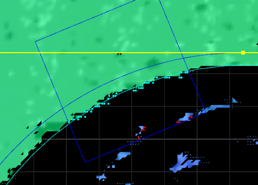
These settings work together to let you set a partial path and exclude part of the data. In the following close-up image of a circular feature, the dark blue path starts to the right of the notch, continues counter-clockwise around the circular feature, and ends to the left of it.
Angle Start is the starting angle, around the Z axis on the XY plane, for the circular path along which calipers are placed. Setting this to 0 aligns the start angle with the positive direction of the X axis. Angle Span is the length of the circular path along which calipers are placed. |
||
|
Path Spacing |
Sets the spacing between paths in the calipers used to extract the profiles that determine the edge. A higher number of paths results in a higher number of edge points, which makes the fitting of the edge line more accurate. However, a higher number of edge points results in a greater tool execution time. When Path Spacing is set to 0, the resolution of the scan data is used as the basis for spacing. |
||
|
Path Width |
The size of the windows perpendicular to the path used to calculate an average for each data point on a path profile. Useful to average out noise along the path caused by reflections, and so on.
If Path Width is set to 0, no averaging is performed (only the data point under the path is used). For averaging along the path, use Step Smoothing (see below). |
||
|
Absolute Threshold |
When Use Intensity is disabled, the setting specifies the minimum height difference between points on a path profile for that step to be considered for an edge point. The setting can be used to exclude smaller steps on a part that should not be considered for an edge, or to exclude height differences caused by noise. When used in conjunction with Relative Threshold, Absolute Threshold is typically set to a small value, greater than the general surface roughness.
When Use Intensity is enabled, the setting specifies the minimum difference in intensity. (Acquire Intensity must enabled in the Scan Mode panel.) |
||
|
Use Relative Threshold |
When this option is enabled, the Relative Threshold field is displayed. |
||
|
Relative Threshold |
The value for the relative threshold. The tool calculates a relative threshold by scaling the greatest height or intensity difference found on the path profiles by the percentage in Relative Threshold. This lets you configure the tool without knowing the actual step height in advance, and is useful for edges with varying step height. For a height or intensity difference to be considered a valid step, both Absolute Threshold and Relative Threshold must pass. |
||
|
Step Smoothing |
The size of the windows along the path used to calculate an average for each data point on a path profile. The setting is useful for averaging out noise. If Step Smoothing is set to 0, no averaging is performed (only the data point under the path is used). For averaging perpendicular to the path, use Path Width (see above). |
||
|
Step Width |
The distance, along a path profile, separating the points used to find steps on a path profile.
The setting is useful when you must detect a slope as an edge, rather than a sharply defined edge: setting Step Width to a value greater than the width of the edge ensures that the tool measures the height difference between the flat regions on either side of the edge. As a result, the height of the step is accurately measured, and the edge is correctly located.
|
||
|
Max Gap |
Fills in regions of missing data caused by an occlusion near the desired edge. Use this setting when continuity on the target is expected. When Max Gap is set to a non-zero value, the tool holds and extends the last data point on the low side next to an edge across a gap of null points, up to the distance specified in Max Gap.
|
||
|
Include Null Edges |
Indicates whether null points (points where no height or intensity value is available, due to dropouts or regions outside of the measurement range) are filled with the value in Null Fill Value as a general “background level.” If Use Intensity (see above) is enabled, the intensity value in Intensity Null Fill Value is also used. A typical example is a discrete part produced by the part detection of an object sitting on a flat background (for more information on part detection, see Profile Part Detection). The background is not visible in the part, so the tool assumes that any null region are at the background level.
|
||
|
Null Fill Value |
The height value (in mm) used to replace null points not filled by Max Gap when Include Null Edges is enabled. |
||
|
Intensity Null Fill Value |
The intensity value (0-255) used to replace null points when Include Null Edges and Use Intensity are enabled. |
||
|
Mask Regions |
Lets you enable up to five regions that you can use to mask data you want the tool to ignore. You can resize and reposition the mask regions using the mouse in the data viewer, or by configuring values manually in the Mask Region sections the tool displays in the tool settings for each region. You can only set the rotation of the mask regions manually by modifying the region's Z angle parameter. By default, when you add multiple mask regions, they are initially placed in the same position, one on top of the other. |
||
|
Reference Plane |
Uses the output of a Surface Plane tool as a reference plane. Useful to correct the scan data if the target is slightly tilted. When Show Advanced Parameters is unchecked and Reference Plane is set to a plane, the plane is ignored. |
||
|
Fit Type |
The method the tool uses to calculate the roundness of the feature. One of the following: Least Square Circle (LSC) Minimum Zone Circle (MZC): If you choose this method, set the circle the tool uses with the Which Circle parameter. Maximum Inscribed Circle (MIC): Typically used to measure the inner edge of a circular feature, such as a hole. Minimum Circumscribed Circle (MCC): Typically used to measure the outer edge of a circular feature. |
||
|
Which Circle |
Tells the tool which circle (Inner or Outer) to use when Minimum Zone Circle is the fit method in Fit Type. |


Outputs
Most tools provide measurements, geometric features, or data as outputs.

Outputs section with a measurement expanded to show user-configurable decision min/max fields and an external ID
You configure the Min and Max parameters by expanding the measurement in the Outputs section. In order for a measurement to return a Pass decision, the measurement must be between maximum and minimum values; the range is inclusive.
| Measurement | Illustration |
|---|---|
|
X Y Returns the X and Y position of the center of the fitted circle, respectively. |
|
|
Radius Returns the radius of the fitted circle. |
|
|
Roundness Returns the roundness or circularity of the edge points with respect to the reference circle of the selected roundness error method set in Fit Type. |
|
|
Min Error Max Error These measurements return information on the points furthest inside and outside the fitted circle, respectively. |


| Type | Description |
|---|---|
| Center Point |
The center of the fitted circle. |
| Circle |
The fitted circle. |
| Min Error Point | The point of minimum error which is furthest inside of the circle. |
| Max Error Point | The point of maximum error which is furthest outside of the circle. |
|
|
For more information on geometric features, see Geometric Features. |