Surface Sphere
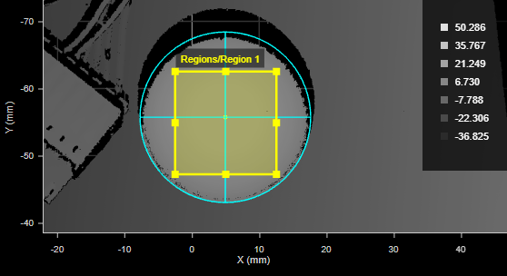
The Sphere tool lets you compute characteristics of a scanned sphere by specifying a region to inspect.

|
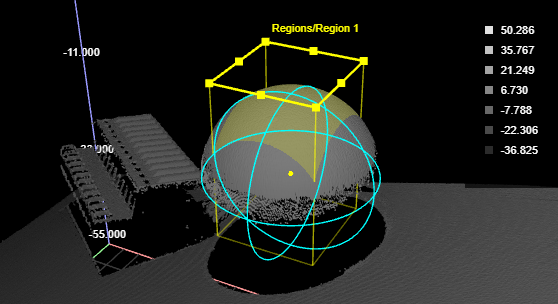
For the tool to work properly, the tool's region must usually be enabled and properly placed to include only the sphere's scan data. |
For information on adding, managing, and removing tools, as well as detailed descriptions of settings common to most tools, see Tool Configuration.
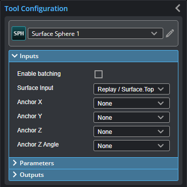
Inputs
You configure the tool's inputs in the expandable Inputs section.
|
|
To use a measurement as an anchor, it must be enabled and properly configured in the tool providing the anchor. For more information on anchoring, see Measurement Anchoring. |
| Name | Description |
|---|---|
| Enable Batching |
For more information on arrays, batching, and aggregating, see Arrays, Batching, and Aggregation. |
|
Surface Input |
The data the tool applies measurements to or processes. This tool can optionally take an array as input. For more information, see Arrays, Batching, and Aggregation. |
|
Anchor X Anchor Y Anchor Z |
The X, Y, or Z measurement of another tool that this tool uses as a positional anchor. Positional anchors are optional. |
| Anchor Z Angle |
The Z Angle measurement of another tool to use as a rotational anchor for this tool. Rotational anchors are optional. |
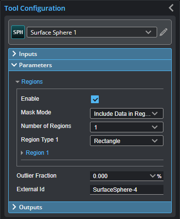
Parameters
You configure the tool's parameters in the expandable Parameters section.
| Parameter | Description |
|---|---|
|
Regions |
When expanded, displays the region- and mask-related settings. |
|
Enable |
Enables regions and displays the region- and mask-related settings (see below). |
|
Mask Mode Number of Regions Region Type {n} Region {n} |
When you enable regions (see above), the tool displays additional settings related to the region type. For details on the regions supported by this tool and their settings, see Flexible Regions. For general information on regions and the difference between standard and "flexible" regions, see Regions. In order for the tool to correctly fit a sphere to the scan data, you must set the region so that it only contains data from the sphere on the target.
|
|
Outlier Fraction |
The percentage of outlier points to exclude. Setting this to a small value can help the tool fit a better sphere when noise is present. |
|
External ID |
The external ID of the tool that appears in GoHMI Designer. For more information, see GoHMI and GoHMI Designer. |
Outputs
Most tools provide measurements, geometric features, or data as outputs.
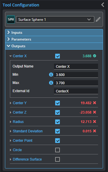
Outputs section with a measurement expanded to show user-configurable decision min/max fields and an external ID
You configure the Min and Max parameters by expanding the measurement in the Outputs section. In order for a measurement to return a Pass decision, the measurement must be between maximum and minimum values; the range is inclusive.
| Measurement | Illustration |
|---|---|
|
Center X, Center Y, Center Z These measurements determine the X, Y, Z position of the center of the sphere, respectively. |
|
|
Radius Determines the radius of the sphere. |
|
|
Standard Deviation Determines the error of the points compared to the computed sphere. It is defined as the square root of the variance of the distance of every point to the computed sphere. |
|


| Type | Description |
|---|---|
| Center Point |
The center of the circle encompassing the widest part of the fitted sphere. |
| Circle |
The circle encompassing the widest part of the fitted sphere. |
|
|
For more information on geometric features, see Geometric Features. |
| Type | Description |
|---|---|
|
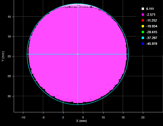
Difference Surface |
Shows the fit error at each point in the height map.
|