Image Mode
In Image mode, the data viewer displays images directly from a sensor's camera or cameras, as well as other information.
In this mode, depending on your sensor model, you can use the data viewer to display profile exposure information (see Exposure Information) and spot and dropout information (see Spots and Dropouts) that can be useful in properly setting system exposure for scanning, and for troubleshooting stray light or ambient light problems.
Gocator sensors can't generate 3D points in over-saturated areas (indicated with red) or in under-exposed areas (indicated with blue). If it's not possible to set a single exposure to capture the entire object target with minimal red or blue areas appearing in Image mode, you can try enabling the Multiple exposure feature; the sensor will then combine the exposures to get the best scan data possible. Choose the exposure you want to examine in the Displayed Outputs panel to view each exposure and tune one high exposure for dark areas on the target and one low exposure for bright areas on the target. Note that multiple exposures reduce the maximum speed the sensor can run at.

|
Not all sensor models indicate over-exposed areas (red). |
The correct tuning of exposure depends on the reflective properties of the target material and on the requirements of the application. You should carefully evaluate the exposure settings for each application.
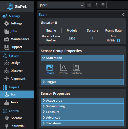
To view Image data, you must set the system to Image mode before scanning, in the Acquire > Scan page > Scan Mode section.
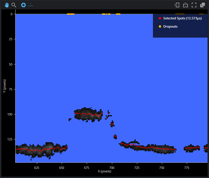
In the following:
-
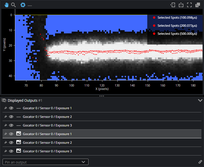
Red dots are the "spots" found by the sensor, which are used to create the data points in scan data.
-
The grayscale squares represent the intensity value of a camera pixel.
-
Blue squares (pixels) are underexposed. On some sensors, red squares represent pixels that are overexposed.
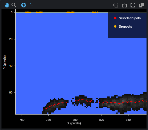
Yellow dots along the top represent dropouts. For more information on spots and dropouts, see Spots and Dropouts.
Exposure Information
In Image mode, you can display exposure-related information. This information can help you correctly adjust the exposure. (For information on setting exposure, see Exposure .)
To display exposure information in the data viewer, click the Exposure button ( ) at the upper left of the data viewer.
Exposure information is listed in the Displayed Outputs panel at the bottom of the data viewer. If you have set the sensor's exposure to Multiple on the Acquire > Scanpage, and have set more than one exposure, each exposure is listed individually (G2) or as an element available in a drop-down (other sensors). Exposure information is displayed in Image (![]() ) outputs.
) outputs.
To display this information, the output must be set to visible. That is, the "eye" icon must be enabled (![]() ) instead of disabled (
) instead of disabled (![]() ). Note that if you have multiple exposures, only the "top" one is displayed in the data viewer. For example, to see the exposure information for Exposure 3, below, you must hide the Image outputs of Exposure 1 and 2.
). Note that if you have multiple exposures, only the "top" one is displayed in the data viewer. For example, to see the exposure information for Exposure 3, below, you must hide the Image outputs of Exposure 1 and 2.
Spots and Dropouts
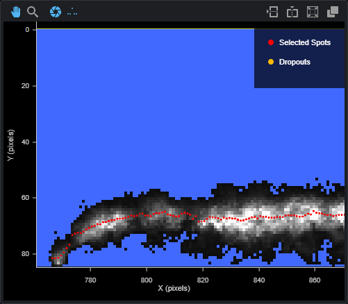
Various settings related to material types (under Scan > Advanced, with Material type set to Custom) and exposure can interact. In Image mode, you can examine how these settings affect. To do this, in Image mode, check the Show Spots option at the top of the data viewer to overlay a representation of the spots in the data viewer.
For more information on the material settings, see Advanced Settings.
In the image below, the white and gray squares represent the light as it appears on the camera sensor.