Gocator Power / IO Connector
The Power / IO connector is a 12-pin, M12 style connector that provides power (camera, optional RMX140 light, and digital output). All inputs and outputs are optically isolated.

|
This connector is rated IP67 only when a cable is connected or when the protective cap is in place. |

View: Looking into the connector on the sensor.
|
Function |
Pin |
Lead |
Description |
|---|---|---|---|
| Not used |
1 |
Brown | - |
| Not used |
2 |
Orange | - |
| Not used |
3 |
Yellow | - |
|
Digital_Out_1 |
4 |
Green |
Optically-isolated output. Open emitter, maximum 10 mA. |
| Not used |
5 |
Blue | - |
| In_GND |
6 |
Purple |
Optically-isolated input ground. 0 VDC |
| DC_ 24V |
7 |
Red (#18) | 24 VDC (±10%) |
| GND_24V |
8 |
Black (#18) | 0 VDC |
|
Opto_PWR |
9 |
Gray |
Power for optically-isolated output. (User-supplied power for driving digital and trigger outputs.) Max. 30 VDC |
| Trigger_In |
10 |
White |
Optically-isolated trigger input. Vin (low) = 0 to 1.0 VDC Vin (high)= 3 to 24 VDC Current (constant-current source) = 3 to 4 mA
For > 24.0 VDC to 36 VDC, connect a 3.3 kΩ external resistor in series. |
| Digital_Out_2 |
11 |
Pink |
Optically-isolated output.
|
| Trigger_Out (strobe) |
12 |
Light Green |
Optically-isolated output. Open emitter, maximum 10 mA. |
| Drain | shell |
Opto-isolated Input Specifications
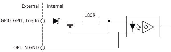
The input can be connected directly to the system for voltages up to 24 VDC. An external resistor is not necessary.
Observe the following levels:
| Parameter | Value |
|---|---|
| Vin (low) | 0 to 1.0 VDC |
| Vin (high) | 3 to 24 VDC |
| Current (constant-current source) | 3 to 4 mA |
The following shows the minimum pulse width:
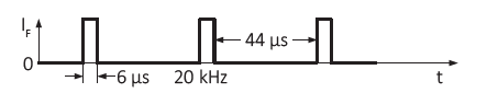
The input signal was driven with 3.3 VDC and no external additional series resistor.
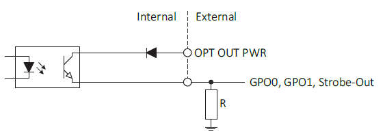
Opto-isolated Output Specifications
| NOTICE | |
|---|---|
|
|
Damage to Gocator 2D Smart Camera by high output current or voltage Exceeding the maximum output voltage or current can damage Gocator 2D Smart Camera. Keep maximum output voltage below 24 VDC and output current below 10 mA. |

|
|
Possible low output voltage Output voltage may drop by approximately 2.5 VDC under full load. |

Observe the following levels:
| Opto-isolated out power | Resistor value (at ~5 mA minimum required current draw)1 |
|---|---|
| 5 VDC | 1.0 kΩ |
| Vin (high) | 2.4 kΩ |
| Current (constant-current source) | 4.7 kΩ |
| 1. A resistor is required when Digital_Out_1, Digital_Out_2, or Trigger_Out (strobe) are connected to devices with a high impedance < 5 mA draw. | |