Tool Chaining
GoPxL’s measurement and processing tools can be linked together: one tool uses another tool’s output as input. This gives you a great deal of control and flexibility when it comes to implementing your application.
The following sections describe the types of output and how you use them as input.
Anchoring Measurements
Tools can use the positional measurements (X, Y, or Z) of other tools as anchors to compensate for minor shifts of parts: anchored tools are “locked” to the positional measurements of the anchoring tool’s measurements. Some tools can also use a Z Angle measurement as an anchor. Typically, you will use measurements from more easily found features on a target—such as an edge or a hole—as anchors to accurately place other positional and dimensional measurements. This can help improve repeatability and accuracy in the anchored tools. Note that anchoring measurements are used to calculate the offsets of the anchored tools: the results from these measurements are not used as part of the anchored tool's measurements.
Anchoring measurements are rendered as overlays on a tool's input data.
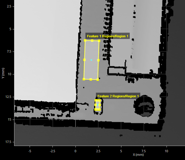
The height of a small PCB component (Feature 2) relative to nearby surface (Feature 1), anchored to positional (X and Y) measurements of the hole (lower right) and to the Z angle of the edge of a larger component to the left.
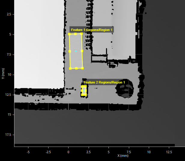
In the following, the part has rotated, but the tool's measurement regions follow the features, ensuring correct measurement.
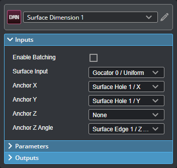
You enable anchoring in the expandable Inputs section of a tool:
Geometric Features
Many of GoPxL’s measurement tools can output data structures such as points, lines, planes, and circles. These structures are called geometric features and contain the components you would expect: a point geometric feature contains X, Y, and Z components (representing the location of the point in 3D space). Examples of point geometric features output by Gocator’s measurement tools are hole center points, the tip and base of studs, or a position on a surface.
Geometric features are rendered as overlays on a tool's input data.
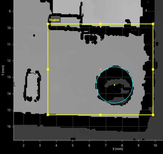
Point geometric feature (a hole's Center Point) rendered on a tool's input as a small yellow circle
Gocator’s “Feature” tools (such as Feature Dimension and Feature Intersect) use geometric features as inputs. For example, because the point geometric feature representing the center of a hole has X, Y, and Z components, you can perform dimensional measurements between it and another geometric feature, such as another hole or an edge. The Feature Create tool takes one or more geometric features as input and generates new geometric features (for example, creating a line from two point geometric features). You can then perform measurements on those features directly in the tool or in other Feature measurement tools. You can also use angle measurements on the newly created features for anchoring.
You enable geometric feature outputs in a tool’s expandable Outputs section:
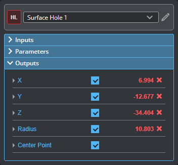
Center Point geometric feature of a Surface Hole tool enabled on Features tab
You enable geometric feature inputs in a tool’s expandable Inputs section:
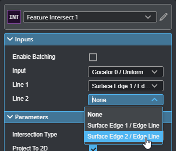
Setting the Line inputs to two different lines to compute their intersection
Geometric features are distinct from the “feature points” used by certain tools to determine which data point in a region should be used in a measurement, for example, the maximum versus the minimum on the Z axis of a data point in a region of interest:
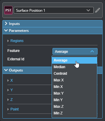
For more information on feature points, see Feature Points.
Tool Data
Some measurement and processing tools can output more complex data, which can be used as input by other tools or SDK applications. The following types of data are available: Profile, Surface, and Generic.
Profile and Surface data produced by a tool is identical in nature to the data produced by a sensor scan, except that they are the processed result from a tool. This kind of data can be used as input in compatible tools.