Feature Line Create
The Feature Line Create tool lets you generate a Line geometric features from geometric features generated by other tools. You can also generate a line from arbitrary positions you provide. The following outputs are available (for more information, see Output Types):
- Line
- Constant line
- Line from two points
- Perpendicular line from point and line
- Perpendicular line from point and plane
- Parallel line from point and line
- Intersect line of two planes
- Projected line on plane
- Bisect projected lines on plane
- Rotate line around point
For more information on geometric features, see Geometric Features.
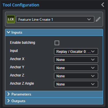
Inputs
You configure the tool's inputs in the expandable Inputs section.
This tool can take an array as input. For more information on arrays, batching, and aggregating, see Arrays, Batching, and Aggregation.
The tool's inputs depend on the output type you choose in the Output parameter. For information on the required inputs and parameters of each output type, see Output Types.
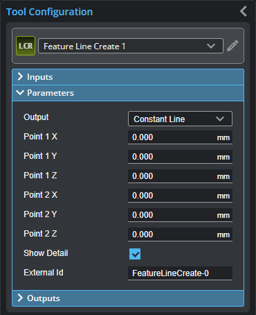
Parameters
You configure the tool's parameters in the expandable Parameters section.
| Parameter | Description |
|---|---|
|
Output |
The type of output the tool generates. Switching between the options changes the input types displayed in Input section and the parameters displayed in the Parameters section. For information on the output types and the related parameters, see Output Types. |
|
Show Detail |
Toggles the display of the input geometric features in the data viewer. |
|
External ID |
The external ID of the tool that appears in GoHMI Designer. For more information, see GoHMI and GoHMI Designer. |
Output Types
The following sections describe the output types available in the tool's Output parameter, in addition to the required inputs and parameters.
Line
The Line output type takes a Line geometric feature as input. This output is useful if the tool takes a feature generated by another Feature Create tool as input, on which you want to perform measurements in a second Feature Create tool. This tool can also be useful if you have developed GDK tools that only generate geometric features (no measurements): you can use this tool to extract those measurements.
The X, Y, and Z measurements return the midpoint of the line. The Z Angle measurement returns the angle of the line around the Z axis. The X angle and Y angle measurements return arbitrary values.
| Inputs | Parameters |
|---|---|
|
Input The Surface or Profile input.
Anchor X, Anchor Y, Anchor Z, Anchor Z Angle The X, Y, and Z position measurements and the Z Angle measurement the tool uses as anchors.
Line The Line geometric feature the tool uses to create another Line geometric feature. |
None. |
Constant Line
The Constant line output type displays parameters you can manually fill in to create a geometric feature. This output type is useful if the scan data from frame to frame is reliably fixed and you want to measure from an arbitrary line to another feature.
| Inputs | Parameters |
|---|---|
|
Input The Surface or Profile input.
Anchor X, Anchor Y, Anchor Z, Anchor Z Angle The X, Y, and Z position measurements and the Z Angle measurement the tool uses as anchors. |
Point 1 X, Point 1 Y, Point 1 Z The X, Y, and Z position, respectively, of the first end point of the constant line.
Point 2 X, Point 2 Y, Point 2 Z The X, Y, and Z position, respectively, of the second end point of the constant line. |
Line from Two Points
The Line from two points output type takes two Point geometric features as input.
A line between the center point of a hole and the corner of the chip.
(The corner is the intersect point resulting from the Feature Intersect tool,
taking the left vertical and lower horizontal line edges of the chip as input.)
The X, Y, and Z measurements return the midpoint of the line. The X, Y, and Z Angle measurements return the angle of the line.
| Inputs | Parameters |
|---|---|
|
Input The Surface or Profile input.
Anchor X, Anchor Y, Anchor Z, Anchor Z Angle The X, Y, and Z position measurements and the Z Angle measurement the tool uses as anchors.
Point 1, Point 2 The two Point geometric features the tool uses as end points to create the line. |
None. |
Perpendicular or Parallel Line from Point and Line
The Perpendicular line from point and line and Parallel line from point and line output types take a Point and a Line geometric feature as input to create another line.
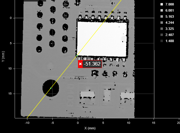
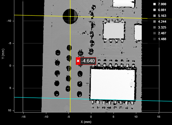
In the following, the tool generates a roughly vertical line (yellow) perpendicular to the input line (cyan line along the left edge of the large integrated circuit), passing through the input point (cyan dot at the center of the hole).
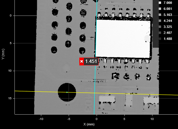
In the following, the tool generates a roughly horizontal line (yellow) parallel to the input line (cyan line along the bottom edge of the large integrated circuit), passing through the input point (cyan dot at the center of the hole).
For both of these types of line output, the X, Y, and Z measurements return the position of the point.
For perpendicular line output, the X, Y, and Z angle measurements return the angles of the line.
For parallel line output, the Z angle measurement returns the angle of the line; the X and Y angle measurements both return arbitrary values.
| Inputs | Parameters |
|---|---|
|
Input The Surface or Profile input.
Anchor X, Anchor Y, Anchor Z, Anchor Z Angle The X, Y, and Z position measurements and the Z Angle measurement the tool uses as anchors.
Point The Point geometric feature the tool uses to create the line.
Line The Line geometric feature the tool uses to create the line. |
None. |
Perpendicular Line from Point to Plane
The Perpendicular line from point to plane output type generates a perpendicular line from a point up to a plane.
| Inputs | Parameters |
|---|---|
|
Input The Surface or Profile input.
Anchor X, Anchor Y, Anchor Z, Anchor Z Angle The X, Y, and Z position measurements and the Z Angle measurement the tool uses as anchors.
Point The Point geometric feature the tool uses to create the line.
Plane The Plane geometric feature the tool uses to create the line. |
None. |
Intersect Line of Two Planes
The Intersect line of two planes output type takes two plane geometric features as input and creates a line at their intersection.
The X, Y, and Z measurements return the midpoint. The X, Y, and Z Angle measurements return the angle of the line.
| Inputs | Parameters |
|---|---|
|
Input The Surface or Profile input.
Anchor X, Anchor Y, Anchor Z, Anchor Z Angle The X, Y, and Z position measurements and the Z Angle measurement the tool uses as anchors.
Plane 1, Plane 2 The two Plane geometric feature the tool uses to create the line. |
None. |
Projected Line on Plane
The Projected line on a plane output type takes a Line and a Plane geometric feature to create a line projected onto a plane.
| Inputs | Parameters |
|---|---|
|
Input The Surface or Profile input.
Anchor X, Anchor Y, Anchor Z, Anchor Z Angle The X, Y, and Z position measurements and the Z Angle measurement the tool uses as anchors.
Line The Line geometric feature the tool uses to create the line.
Plane The Plane geometric feature the tool uses to create the line. |
Projection Direction One of the following: Perpendicular to Plane or Along Z Axis. |
Bisect Projected Lines on Plane
The Bisect projected lines on plane output type creates a Line and a Plane geometric feature as input and creates a line.
| Inputs | Parameters |
|---|---|
|
Input The Surface or Profile input.
Anchor X, Anchor Y, Anchor Z, Anchor Z Angle The X, Y, and Z position measurements and the Z Angle measurement the tool uses as anchors.
Line The Line geometric feature the tool uses to create the line.
Plane The Plane geometric feature the tool uses to create the line. |
None. |
Outputs
All tools provide measurements, geometric features, or data as outputs.
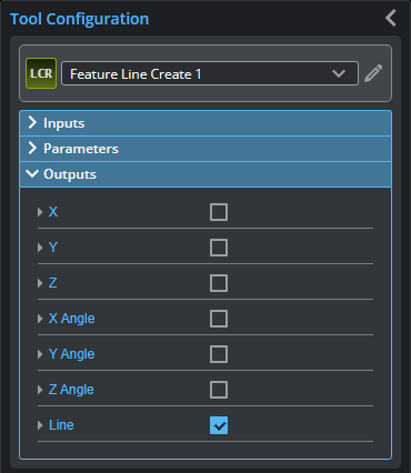
Outputs section with a measurement expanded to show user-configurable decision min/max fields and an external ID
You configure the Min and Max parameters by expanding the measurement in the Outputs section. In order for a measurement to return a Pass decision, the measurement must be between maximum and minimum values; the range is inclusive.
For information specific to the different output types, see Output Types.
| Measurement |
|---|
|
X, Y, Z The X, Y, and Z positions of the midpoint of the line described by the Point geometric features. For more information, see the sections above. |
|
X Angle, Y Angle, Z Angle The X, Y, and Z angles of the line. For more information, see the sections above. |
| Type | Description |
|---|---|
|
Line |
The generated Line geometric feature. |