Mesh Bounding Box

|
This tool is only intended for use with G2 sensors. |
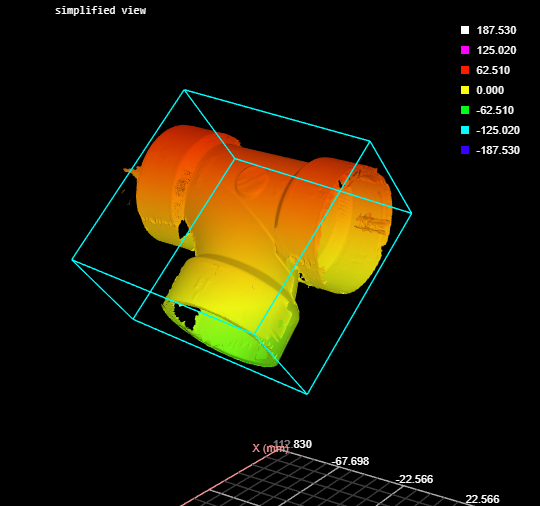
The Mesh Bounding Box tool takes in Mesh scan data (produced by the Surface Mesh tool and some other Mesh tools) and returns measurements related to the bounding box encapsulating the scan data in the region of interest, such as the rotation of the bounding box, the dimensions of the bounding box, and its location. In addition to a Point geometric feature, the tool returns the Mesh data in the bounding box. You can apply one of the other Mesh tools to this data, or after extracting Surface data using Mesh Projection or Mesh Plane, you can apply any built-in or custom GDK-based tool to the extracted surface data.
Inputs
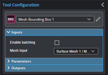
You configure the tool's inputs in the expandable Inputs section.
| Name | Description |
|---|---|
| Enable Batching |
For more information on arrays, batching, and aggregating, see Arrays, Batching, and Aggregation. |
|
Mesh Input |
The data the tool applies measurements to or processes. |
Parameters
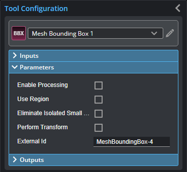
You configure the tool's parameters in the expandable Parameters section.
| Parameter | Description |
|---|---|
|
Enable Processing |
Causes the tool to start processing scan data from individual sensors. Make sure to properly configure the tool before enabling this option. |
|
Use Region |
Determines whether the tool limits the bounding box fit to Mesh data in a user-defined region to fit a bounding box. Enabling this option displays parameters you use to define the size and position of the region. |
|
Eliminate Isolated Small Surface |
Excludes small, unconnected data from the Mesh output. |
|
Perform Transform Transform Mode |
When Perform Transform is enabled, you can choose the which axes are the major, minor, and tertiary axes. The tool also centers the Mesh data at origin 0. This lets you align the part data however you want. Transform Mode is one of the following:
|
|
External ID |
The external ID of the tool that appears in GoHMI Designer. For more information, see GoHMI and GoHMI Designer. |
Outputs
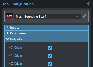
All tools provide measurements, geometric features, or data as outputs.
You configure the Min and Max parameters by expanding the measurement in the Outputs section. In order for a measurement to return a Pass decision, the measurement must be between maximum and minimum values; the range is inclusive.
All outputs provide an external ID (available by expanding the output in the Outputs panel) for optional use in GoHMI Designer. For more information, see GoHMI and GoHMI Designer.
| Measurement |
|---|
|
X Origin Y Origin Z Origin These measurements return the X, Y, and Z position of the center of the fitted bounding box, respectively. |
|
X Angle Y Angle Z Angle The angle of the fitted bounding box around the X, Y, and Z axis, respectively. |
|
Width Length Height The width, length, and height of the fitted bounding box. |
| Type | Description |
|---|---|
|
Point |
A point representing the center of the fitted bounding box. |
|
|
For more information on geometric features, see Geometric Features. |
| Type | Description |
|---|---|
|
Mesh |
The Mesh data contained in the bounding box. |