Mesh Template Matching

|
This tool is only intended for use with G2 sensors. |
|
|
This tool is not supported on A and B revision Gocator 2100 and 2300 sensors that are not accelerated (either by a PC-based application or by GoMax). The tool is supported in emulator scenarios. |
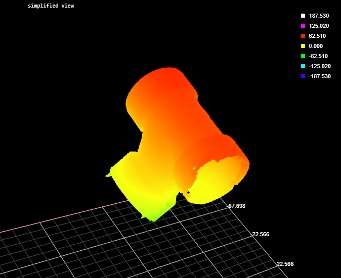
The Mesh Template Matching tool takes in Mesh scan data (produced by the Surface Mesh tool) and a template you previously defined based on a "golden part" (itself created using the Mesh Template Matching tool). The tool returns measurements related to the position and orientation of the scan data relative to the template, such as offsets and rotations, as well as standard deviations between the scan data and the template. The tool can also output Mesh scan data.
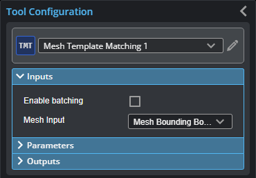
Inputs
You configure the tool's inputs in the expandable Inputs section.
| Name | Description |
|---|---|
| Enable Batching |
For more information on arrays, batching, and aggregating, see Arrays, Batching, and Aggregation. |
|
Mesh Input |
The data the tool applies measurements to or processes. |
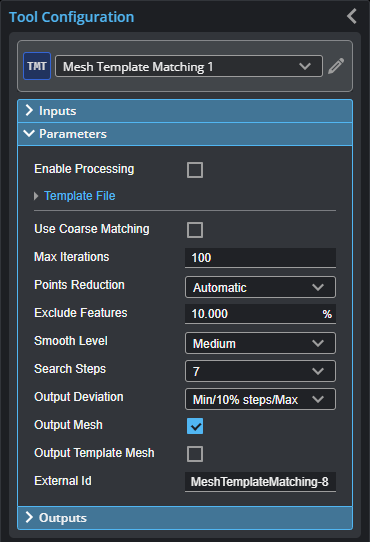
Parameters
You configure the tool's parameters in the expandable Parameters section.
| Parameter | Description |
|---|---|
|
Enable Processing |
When this option is enabled, the tool compares the Mesh data to the loaded template. |
| Template File | Expanding section containing template-related parameters. |
|
Operation Template Name Template File |
The tool's operation mode. One of the following: Normal: When Enable Processing is enabled, the tool compares the Mesh scan data and the loaded template. Load: Displays a list of Mesh template files you can load (in the Template File drop-down). Supports the following three formats:
Save: Saves the current frame of Mesh scan data as a template (in C:\GoTools\Mesh Template Matching\) in BCD format. Type the name of the template in the File Name field, and then check Enable Processing to save the file. A user message is displayed if the template is saved successfully. Note this option is only available if there is no template currently loaded in this tool. Delete: Deletes the template file you select in the Template File field. Refresh: Refreshes the template file list. Remove: Unload an existing template to make the Save option visible. So that user is aware that just the current input mesh data will be declared and saved as a template, when selecting the Save option. |
|
Use Course Matching |
Enable this parameter when the body surfaces to be matched are not symmetrical, and the original orientation and position deviate significantly from the measured data set. |
|
Max Iterations |
The maximum number of iterations the tool uses to match the Mesh scan data with the template. This parameter can be used to speed up the optimization process to some degree. Typically, leave this at the default value. |
|
Points Reduction |
Controls the number of points used in the matching process, which can improve processing time. |
|
Exclude Features |
Use this when there are high or low features on the part that should not be included in the matching. For example, at 10%, the tool excludes 10% of the points with maximum or minimum deviation from the matching process. |
|
Smooth Level |
The amount of smoothing the tool applies. LMI recommends leaving this setting at its default. |
|
Search Steps |
Determines the neighborhood level in which to search for connection point pairs. |
|
Output Deviation |
Determines which deviations are output as measurements, which can be a combination of minimum and maximum, and a set of Deviation (x %) measurements (with the specified step between them). Can also be set so that no deviations are output. Use this to get a rough idea of the distribution of the deviation values (or a histogram of the deviations). |
|
Output Mesh |
Outputs the transformed mesh. |
|
Output Template Mesh |
Outputs a mesh template. |
|
External ID |
The external ID of the tool that appears in GoHMI Designer. For more information, see GoHMI and GoHMI Designer. |
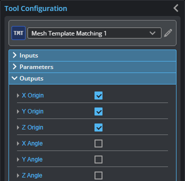
Outputs
All tools provide measurements, geometric features, or data as outputs.
You configure the Min and Max parameters by expanding the measurement in the Outputs section. In order for a measurement to return a Pass decision, the measurement must be between maximum and minimum values; the range is inclusive.
All outputs provide an external ID (available by expanding the output in the Outputs panel) for optional use in GoHMI Designer. For more information, see GoHMI and GoHMI Designer.
| Measurement |
|---|
|
X Origin Y Origin Z Origin X Angle Y Angle Z Angle These measurements represent the transform matrix that matches the input mesh against the template. |
|
Standard Deviation The standard deviation of pairs of matching points. |
|
Minimum Maximum The minimum and maximum deviation of pairs of matching points. |
|
Deviation (x%) The deviations of pairs of matching points, sorted into stepped percentiles. You set the number of steps using the Output Deviation parameter. |
| Type | Description |
|---|---|
|
Mesh |
The transformed Mesh. Only listed if the Output Mesh parameter is enabled. |
|
Mesh Template |
A template Mesh. Only listed if the Output Template Mesh parameter is enabled. |