Surface Ball Bar
The Surface Ball Bar tool returns measurements useful for calibrating systems using a ball bar, particularly systems that include a robot.
Inputs
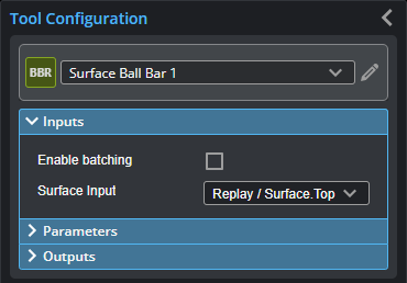
You configure the tool's inputs in the expandable Inputs section.
| Name | Description |
|---|---|
| Enable Batching |
Leave this setting unchecked. |
|
Surface Input |
The data the tool applies measurements to or processes. |
Parameters
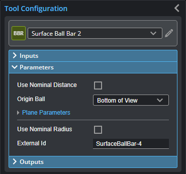
You configure the tool's parameters in the expandable Parameters section.
| Parameter | Description |
|---|---|
|
Use Nominal Distance |
When enabled, displays Nominal Distance and Distance Tolerance settings. Set these to the distance between the balls of the ball bar (refer to the specifications of the ball bar) and the tolerance you need. This can be useful to ensure invalid results due to false or inaccurate detection are rejected. |
|
Origin Ball |
Determines which ball is used as the origin. The Bottom of View option selects the ball at the bottom of the data viewer in the web interface. |
|
Plane Parameters |
Enables advanced plane settings. For UR integration, you should leave the settings at their default. These parameters allow ensuring the plane detection is accurate and robust to variations. |
|
Use Nominal Radius |
When enabled, displays Nominal Radius {n} settings. Set these to the radius of the balls of the ball bar (refer to the specifications of the ball bar) and the tolerance you need. This can be useful to ensure invalid results due to false or inaccurate detection are rejected. The tool uses these as a starting point and will not necessarily reject targets based on these. |
|
External ID |
The external ID of the tool that appears in GoHMI Designer. For more information, see GoHMI and GoHMI Designer. |
Outputs
| Measurement |
|---|
|
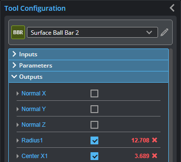
Normal X / Y / Z These measurements return the X, Y, and Z components of the normal vector of the surface surrounding the calibration target. |
|
Radius1 Radius2 These measurements return the radius of each ball. |
|
Center X1 / Y1 / Z1 Center X2 / Y2 / Z2 These measurements return the X, Y, and Z positions of the centers of the spheres fitted to the balls. Ball 1 (Center X1 / Y1 / Z1) is always used as the origin. (Corresponds to the values returned in Tx / Ty / Tz.) |
|
Distance 3D The direct distance between the centers of the spheres fitted to the balls. |
|
Ix / Iy / Iz Jx / Jy / Jz Kx / Ky / Kz These measurements return the X, Y, and Z components of the I, J, and K unit vectors defining the coordinate system orientation. |
|
Tx / Ty / Tz These measurements return the X, Y, and Z components of the translation vector defining the coordinate system origin location. |
| Type | Description |
|---|---|
|
Difference Surface |
The difference between the scan data and the provided nominal dimensions. Used for diagnostics. |