Surface Part Detection

|
The Surface Part Detection tool is usually used with G3 sensors. |
The Surface Part Detection tool identifies discrete objects in Surface data and then outputs them as Surface data. Surface measurements can then be performed on each object.
|
|
You can isolate and then measure parts using Surface Blob and Surface Segmentation tools (for more information on these tools, see Surface Blob and Surface Segmentation). For a comparison of part detection and these tools, see Isolating Parts from Surface Data. |
Part detection can be performed when Source on the Acquire > Scan page in the Trigger panel is set to Time or Encoder. To use the Time trigger source, the travel speed must be calibrated. To use the Encoder trigger source, the encoder resolution must be calibrated.
For information on adding, managing, and removing tools, as well as detailed descriptions of settings common to most tools, see Tool Configuration.
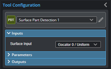
Inputs
You configure the tool's inputs in the expandable Inputs section.
| Name | Description |
|---|---|
|
Surface Input |
The source of data for the tool. |
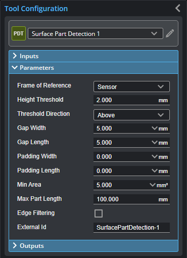
Parameters
You configure the tool's parameters in the expandable Parameters section.
| Parameter | Description |
|---|---|
|
Frame of Reference |
Determines the coordinate reference for surface measurements.
Sensor When Frame of Reference is set to Sensor, the sensor's frame of reference is used.
Part When Frame of Reference is set to Part, all measurements are relative to the center of the bounding box of the part. |
|
Threshold Type |
Determines if parts should be detected above or below the height threshold. |
|
Threshold |
Determines the height threshold for part detection. The setting for Threshold Type (see above) determines if parts should be detected above or below the value in Threshold. Above is typically used to prevent the belt surface from being detected as a part when scanning objects on a conveyor. |
|
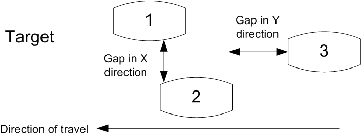
Gap Width Gap Length |
Gap Width and Gap Length determine the minimum separation between objects on the X and the Y axis, respectively. If parts are closer than the gap interval, they will be merged into a single Surface output.
|
|
Pad Width Pad Length |
These parameters are useful when processing part data with third-party software such as HexSight, Halcon, etc. Pad Width and Pad Length control the amount of additional scan data output in the X and Y directions, respectively. The padding can contain data points that were outside the height threshold and excluded from the initial part detection. |
|
Min Area |
Determines the minimum area for a detected part. Set this value to a reasonable minimum in order to filter out small objects or noise. |
|
Max Length |
Determines the maximum length of the part object. When the object exceeds the maximum length, it is automatically separated into two parts. |
|
Edge Filter
|
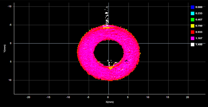
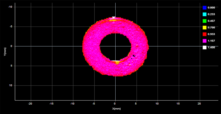
When Edge Filter is enabled, an Edge Filter expanding section is displayed that contains the settings described below. Part scans sometimes contain noise around the edges of the target. This noise is usually caused by the sensor’s light being reflected off almost vertical sides, rounded corners, etc.
Edge Filter disabled (scan shows reflection noise)
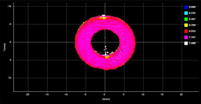
Edge Filter enabled (reflection noise eliminated or reduced)
Edge Filter enabled, Keep Interior enabled |
|
External ID |
The external ID of the tool that appears in GoHMI Designer. For more information, see GoHMI and GoHMI Designer. |
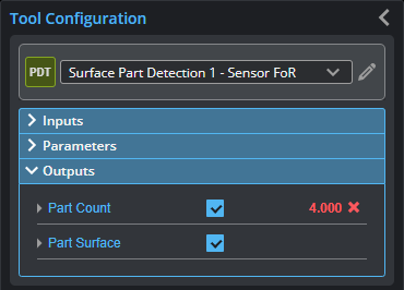
Outputs
All tools provide measurements, geometric features, or data as outputs.
| Measurement |
|---|
|
Part Count The number of parts the engine detects. |
| Type | Description |
|---|---|
| Part Count |
The number of parts detected. |
| Part Surface |
The Surface data of the detected part. |