Surface Generation
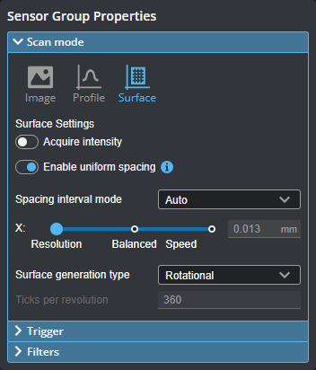
GoPxL provides different ways to generate Surface data, depending on the needs of your application. You configure these Surface generation methods in the Scan Mode section in the Inspect > Scan page. Four modes are available:
- Continuous
- Fixed Length
- Variable Length
- Rotational
Continuous Surface Generation and Part Detection
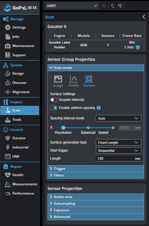
Use this method of surface generation with a transport system such as a conveyor that continuously feeds parts or material under a sensor. The parts or material must have a distinguishable start and stop edge. The sensor continuously generates surfaces of parts that are detected under the sensor. When a sensor is set to continuous Surface generation, you must configure parameters related to part detection.

|
GoPxL also provides part detection through the Profile Part Detection tool. The tool uses the same parameters available with continuous generation Surface mode, but also provides diagnostics that can be useful for troubleshooting. After troubleshooting part detection using this tool, you can copy the settings from the tool to the Scan page. The diagnostics are output as measurements by the tool. Note that the Profile Part Detection has a Frame of Reference parameter not available when using continuous Surface generation. |
| Parameter | Description |
|---|---|
|
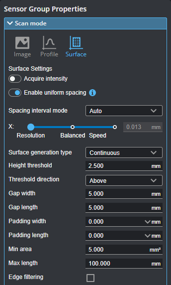
Height Threshold |
Determines the height threshold for part detection. The setting for Threshold Type (see above) determines if parts should be detected above or below the value in Threshold. Above is typically used to prevent the belt surface from being detected as a part when scanning objects on a conveyor. In an Opposite layout, the threshold is applied to the difference between the top and the bottom profile. A target thinner than the threshold value is ignored, including places where only one of either top or bottom is detected. To separate parts by gated external input, set Threshold to the active area Z offset (that is, minimum Z position of the current active area). In the Trigger panel, set Source to Time or Encoder, and check the Gate on External Input checkbox in the Trigger panel; for more information, see Triggers. |
|
Threshold Type |
Determines if parts should be detected above or below the height threshold. |
|
Gap Width Gap Length |
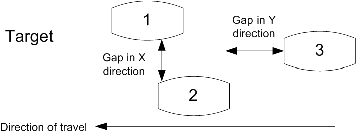
Gap Width and Gap Length determine the minimum separation between objects on the X and the Y axis, respectively. If parts are closer than the gap interval, they will be merged into a single Surface output.
|
|
Padding Width Padding Length |
These parameters are useful when processing part data with third-party software such as HexSight, Halcon, etc. Padding Width and Padding Length control the amount of additional scan data output in the X and Y directions, respectively. The padding can contain data points that were outside the height threshold and excluded from the initial part detection. |
|
Min Area |
Determines the minimum area for a detected part. Set this value to a reasonable minimum in order to filter out small objects or noise. |
|
Max Length |
Determines the maximum length of the part object. When the object exceeds the maximum length, it is automatically separated into two parts. |
|
Edge Filter
|
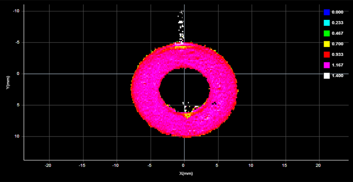
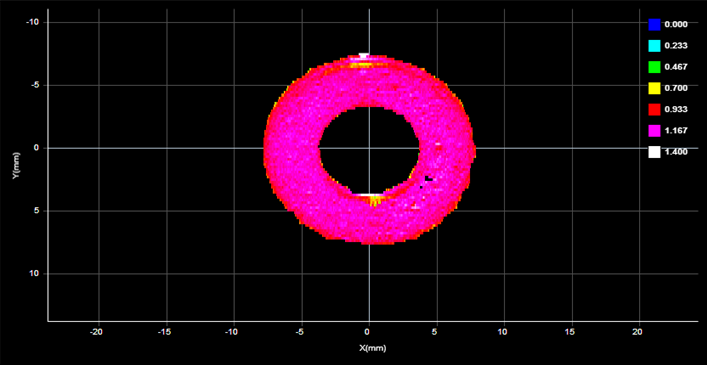
When Edge Filter is enabled, an Edge Filter expanding section is displayed that contains the settings described below. Part scans sometimes contain noise around the edges of the target. This noise is usually caused by the sensor’s light being reflected off almost vertical sides, rounded corners, etc. (The following screenshots are from a G2 sensor.)
Edge Filter disabled (scan shows reflection noise)
Edge Filter enabled (reflection noise eliminated or reduced)
Edge Filter enabled, Keep Interior enabled |
|
Keep Interior |
The Keep Interior setting limits filtering to the outside edges of the target. |
|
Edge Width Edge Length |
The Edge Width and Edge Length settings represent the size of the filter on the X axis and the Y axis, respectively. |
|
External ID |
The external ID of the tool that appears in GoHMI Designer. For more information, see GoHMI and GoHMI Designer. |
Fixed Length
The sensor generates surfaces of a user-configurable fixed length. You must set the length and the start trigger the sensor uses to produce Surface data.
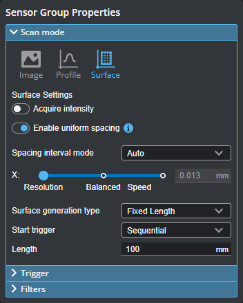
When you set the Surface generation type to Fixed Length, the sensor generates surfaces of a user-configurable fixed length. Like the Profile Part Detection tool, Fixed Length mode is used when material or parts continuously pass under the sensor, typically on a conveyor. Unlike the tool-based method, parts and material do not have distinguishable start and stop edge.

For correct length measurement, you should ensure that motion is calibrated (that is, you have set the encoder resolution for encoder triggers or travel speed for time triggers, in System page > Alignment panel.
To use this method of surface generation, under Inspect > Scan, be sure to select Surface mode and configure the following parameters.
Start Trigger
The following types of start triggers are available:
- Sequential: Continuously generates back-to-back fixed length surfaces.
- External Input: A pulse on the digital input triggers the generation of a single surface of fixed length.
- Software Trigger: Allows starting fixed length surfaces on command from PLC or PC.
Length
The fixed length of surface to generate.
For more information on connecting external input to a sensor, see Digital Input.
Variable Length
The sensor generates surfaces of variable length. Profiles collected while the external digital input is held high are combined to form a surface. If the value of the Max Length setting is reached while external input is still high, the next surface starts immediately with the next profile. This mode is typically used in robot-mounted applications, for example, measuring the dimensions of different parts on an engine block.
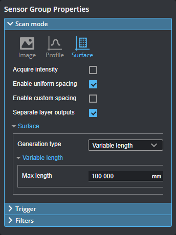

For correct length measurement, you should ensure that motion is calibrated (i.e., encoder resolution for encoder triggers or travel speed for time triggers).
For more information on connecting external input to a sensor, see Digital Input.
Rotational
The sensor reorders profiles within a surface to be aligned with the encoder’s index pulse. That is, regardless of the radial position the sensor is started at, the generated surface always starts at the position of the index pulse. If the index pulse is not detected and the rotation circumference is met, the surface is dropped and the Encoder Index Drop indicator will be incremented. This mode is typically used in applications where measurements of circular objects or shafts need to be taken, such as tire tread inspection, or label positioning on bottles.

