Profile Thickness
The Thickness tool lets you perform thickness measurements between the two profiles you specify.
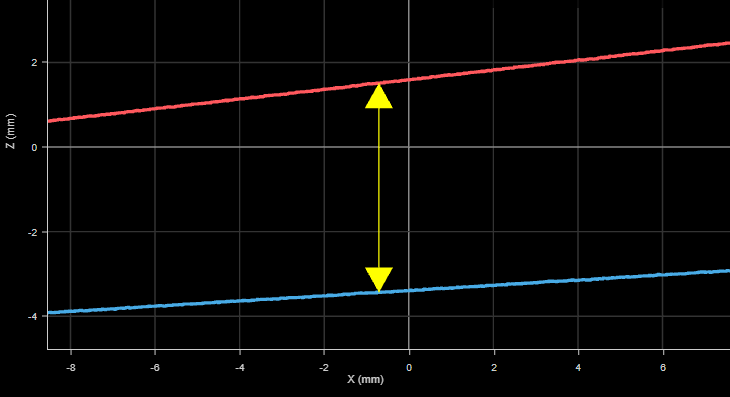
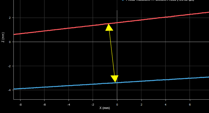
The tool also lets you specify an angle measurement relative to which the tool performs the thickness measurements, up to a maximum of 20 degrees, to compensate for minor tilt of the target. To get the compensation angle, you could first fit a straight line to the top profile using the Profile Line tool, and pass that tool's Angle measurement to Profile Thickness. (For information on Profile Line, see Profile Line.)
For information on adding, managing, and removing tools, as well as detailed descriptions of settings common to most tools, see Tool Configuration.
Inputs
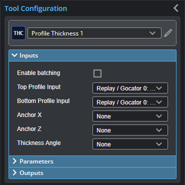
You configure the tool's inputs in the expandable Inputs section.

|
To use a measurement as an anchor, it must be enabled and properly configured in the tool providing the anchor. For more information on anchoring, see Measurement Anchoring. |
| Name | Description |
|---|---|
| Enable Batching |
For more information on arrays, batching, and aggregating, see Arrays, Batching, and Aggregation. |
|
Top Profile Input Bottom Profile Input |
The top and bottom profiles the tool uses to perform thickness measurements. If Enable Batching is checked, each input takes an array. |
|
Anchor X or Anchor Z |
The X or Z measurement of another tool that this tool uses as a positional anchor. Positional anchors are optional. |
| Thickness Angle |
An angle measurement from another tool that the Thickness tool uses for the angle of the thickness measurement. If no angle is provided, the thickness measurement is perpendicular to the X axis.
|
Parameters
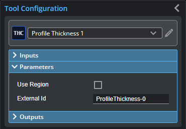
You configure the tool's parameters in the expandable Parameters section.
| Parameter | Description |
|---|---|
|
Use Region |
When enabled, displays Region parameters (see below). When disabled, the tool uses all data. |
|
Region |
The region to which the tool's measurements will apply. For more information, see Regions. |
|
External ID |
The external ID of the tool that appears in GoHMI Designer. For more information, see GoHMI and GoHMI Designer. |
Outputs
All tools provide measurements, geometric features, or data as outputs.
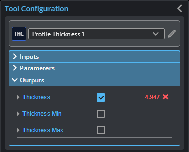
Outputs section with a measurement expanded to show user-configurable decision min/max fields and an external ID
You configure the Min and Max parameters by expanding the measurement in the Outputs section. In order for a measurement to return a Pass decision, the measurement must be between maximum and minimum values; the range is inclusive.
| Measurement |
|---|
|
Thickness The thickness measured in the scan data. |
|
Thickness Min The minimum thickness measured in the scan data. |
|
Thickness Max The maximum thickness measured in the scan data. |