Advanced Settings
The settings in the Advanced section on the Inspect > Scan page let you configure spot detection (which determines how the sensor handles different material characteristics), camera gain, and other advanced settings.
Material Type and Spot Detection
You can configure data acquisition to suit different types of target materials.
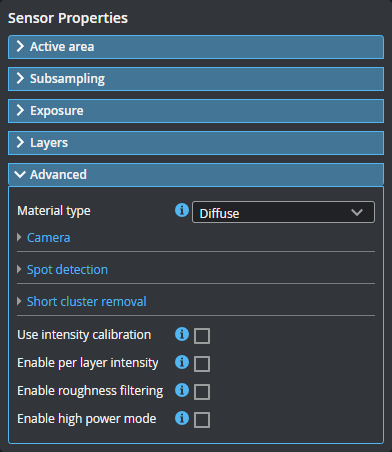
You can select preset material types in the Material type setting in the Advanced panel on the Inspect > Scan page. The Diffuse material option is suitable for most materials.
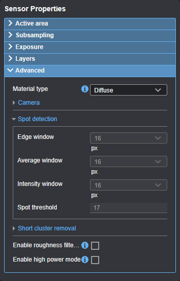
When Material type is set to Diffuse, the sensor uses the following spot detection parameters:
| Edge window | Average window | Intensity window | Spot threshold |
|---|---|---|---|
|
16 |
16 |
16 |
17 |
When Material type is set to Custom, you can set camera gain and modify spot detection. Some sensor models support both analog and digital gain, whereas others only support digital gain. For more information, see Spot Detection and Camera Gain.
Spot Detection
When adjusting the spot detection parameters, it's best to observe how the changes you make to these parameters affect the detected spots in Image mode, and also how that affects the resulting profile in Profile mode.
You can only adjust spot detection parameters when Material type is set to Custom. Set this to custom if the default values do not provide adequate spot detection.
The windows for spot detection (displayed in Image mode) and intensity (as displayed in Profile or Surface mode when Acquire intensity is enabled) are separate. The Average window setting is used in the background for spot detection. The Intensity window setting is used to define the intensity displayed in Surface mode.
The effect of the Intensity window setting can’t be seen in Image mode or Profile mode, only in Surface data or intensity data when Acquire intensity is enabled.
| Setting | Description |
|---|---|
|
Edge window |
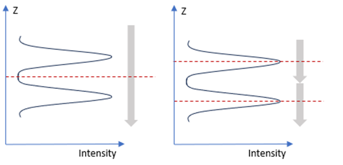
Sets the height of the window, in pixels, used to calculate the spot’s exact peak Z position, using an average of the intensity in the window. The value range is even numbers from 2 to 16. For all non-transparent materials, a value of 16 usually produces the most accurate Z measurement. For thin, transparent materials, a lower value helps to detect all surfaces of the material. In these cases, lower the Edge window value until all surfaces are visible. The image below illustrates transparent material with top and bottom layers, and shows the effect of different edge window sizes. Left: A longer edge window moving over Z (the long vertical gray arrow) results in only one maximum intensity peak (the single red dotted line) being detected, and therefore only one layer. Right: A shorter edge window results in both layers being correctly detected.
|
|
Average window |
Sets the length of the window, in pixels, used to calculate the average intensity for signal detection. The spot is detected if the calculated average intensity is greater than the value in Spot threshold. The value range is even numbers from 2 to 16. Note the following:
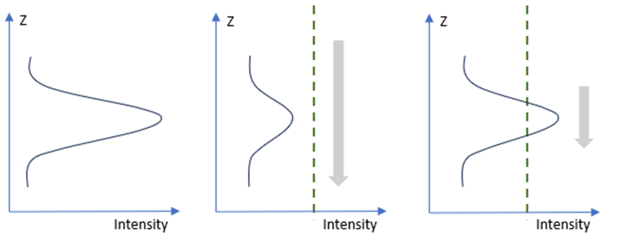
The image below shows the effects of different average window sizes. Left: The raw intensity data is shown. Middle: A longer average window moving over Z (the long vertical gray arrow) results in the averaged intensity staying below the value in Spot threshold (green dotted line) and data is not identified as valid for spot detection. Right: With a shorter average window, the averaged peak intensity exceeds the threshold, and the range above the threshold is identified as valid for spot detection.
The calculated average intensity is not normally reported. To accomplish this, set the layer's Intensity filter type parameter to "Signal detection" (for more information, see Layer-specific parameters (Layer {n})). This may be useful in some thin film applications. |
|
Intensity window |
Sets the length of the window, in pixels, used to define the mean intensity value of the detected spots, which is then reported as the spot’s intensity. When the intensity window is long, the reported intensity values are lower due to averaging, and noise is minimized. The value range is even numbers from 2 to 16. Note the following:
|
|
Spot Threshold |
Sets the minimum intensity for spot detection. The range is from 1 to 150. The spots are detected when the averaged intensity value exceeds the spot threshold value. Note that the value set in Average window has an effect on the intensity value. Note the following:
|
Camera Gain
| Setting | Description |
|---|---|
|
Camera Gain |
|
|
Digital camera gain can be used when the application is severely exposure limited, yet dynamic range is not a critical factor. |
Other Advanced Settings
| Setting | Description |
|---|---|
| Use intensity calibration |
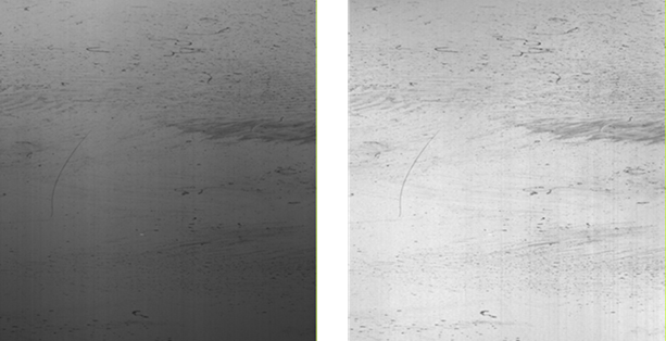
If this parameter is enabled, slightly uneven distribution of illumination is corrected for intensity values by using the sensor- specific calibration file. Typically the illumination is a bit higher in the middle of the field of view than on the far sides and also in the middle of the measurement range compared to the edges of the range. This setting may be useful in defect detection. The following shows Surface data in Grayscale mode in the data viewer without (left) and with (right) Use intensity calibration enabled.
Only available if you have enabled Acquire intensity in the Scan mode section (see Scan Modes and Intensity). |
| Enable per layer intensity |
When this parameter is enabled, you can set the Intensity filter type parameter for each layer individually. Otherwise, an "Average intensity" filter is used for all layers. Only available if you have enabled Acquire intensity in the Scan mode section (see Scan Modes and Intensity). |
| Enable roughness filter | If enabled, a median Z of 3 pixels is applied to remove the outliers. |
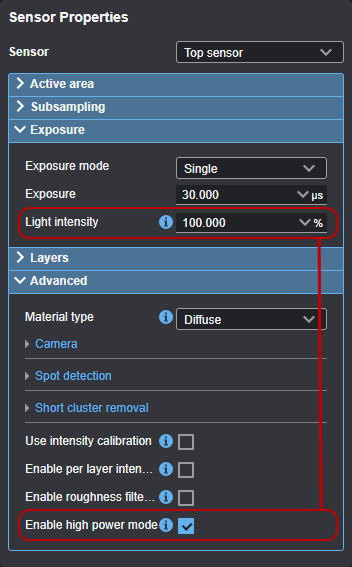
| Enable high power mode |
If enabled, a Light intensity setting is displayed in the Exposure section to let you set the LED light intensity to a value greater than 100%. Note that enabling high power mode can limit frame rates. Updating the light intensity can take several seconds to apply. For more information on the Light intensity setting, see the topic on the exposure mode you have chosen under Exposure and Light Intensity.
|
| Short cluster removal |
A cluster is a set of points where the neighboring points fall within a specified X and Z window. Cluster removal is done after layer sorting but before detect missing layer.
The Clustering X distance and Clustering Z distance parameters connect points to clusters. Minimum cluster width removes clusters smaller than the set length. When short cluster removal is enabled, you must set the following parameters.
Clustering X distance Maximum X distance (µm) to the nearest point in a cluster.
Clustering Z distance Maximum Z distance (µm) to the nearest point in a cluster.
Minimum cluster width If a cluster is shorter than Minimum cluster width (µm), it will be removed. In the image above, the first three clusters have been recognized using the window of Clustering X distance (1) and Clustering Z distance (2). (The green lines are together one cluster, because its gaps are shorter than Clustering X distance.) Then the red cluster is removed because it is shorter than Minimum cluster width (3). This tool can be useful to remove noise from the first layer, caused by dust, for example. |