Feature Circle Create
The Feature Circle Create tool lets you generate a Circle geometric features from geometric features generated by other tools. You can also generate a circle from an arbitrary position and radius. The following outputs are available (for more information, see Output Types):
- Constant circle
- Circle from points
- Circle from point and plane
For more information on geometric features, see Geometric Features.
Inputs
You configure the tool's inputs in the expandable Inputs section.
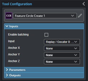
This tool can take an array as input. For more information on arrays, batching, and aggregating, see Arrays, Batching, and Aggregation.
The tool's geometric feature inputs depend on the output type you choose in the Output parameter. For information on the required inputs and parameters of each output type, see Output Types.
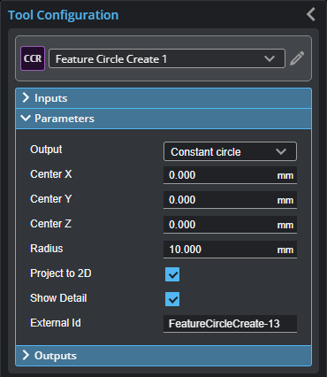
Parameters
You configure the tool's parameters in the expandable Parameters section.
| Parameter | Description |
|---|---|
|
Output |
The type of output the tool generates. Switching between the options changes the input types displayed in Input section and the parameters displayed in the Parameters section. For information on the output types and the required inputs and related parameters, see Output Types. |
|
Project To 2D |
If checked, generates a circle in the XZ plane for Profile mode and in the XY plane for Surface mode. Otherwise, generates a 3D circle. Not shown when Output is set to “Circle from point and plane”. |
|
Show Detail |
Toggles the display of the input geometric features in the data viewer. |
|
External ID |
The external ID of the tool that appears in GoHMI Designer. For more information, see GoHMI and GoHMI Designer. |
Output Types
The following sections describe the output types available in the tool's Output parameter, in addition to the required inputs and parameters.
Constant Circle
The Constant circle output type is useful if scan data from frame to frame is reliably fixed and you want to measure from an arbitrary circle to another feature. When you choose this output type, the tool displays the following parameters you can manually fill in to create a constant circle.
Disable Project To 2D to input an arbitrary normal vector (using the Normal parameters) to get a tilted 3D circle.
| Inputs | Type-Related Parameters |
|---|---|
|
Input The Surface or Profile input.
Anchor X, Anchor Y, Anchor Z The X, Y, and Z offsets the tool will apply to the generated circle. |
Center X, Center Y, Center Z The X, Y, and Z position, respectively, of the center of the constant circle.
Normal X, Normal Y, Normal Z The X, Y, and Z for the normal vector. Only displayed when Project To 2D is disabled.
Radius The radius of the constant circle. |
Circle from Points
The Circle from points output type takes three point geometric features generated by another tool and fits a circle to those points. The circle is always on the XY plane.
When Project To 2D is enabled, the circle is projected to the XY plane. When Project To 2D is disabled, circle is tilted to fit the plane the three point inputs create.
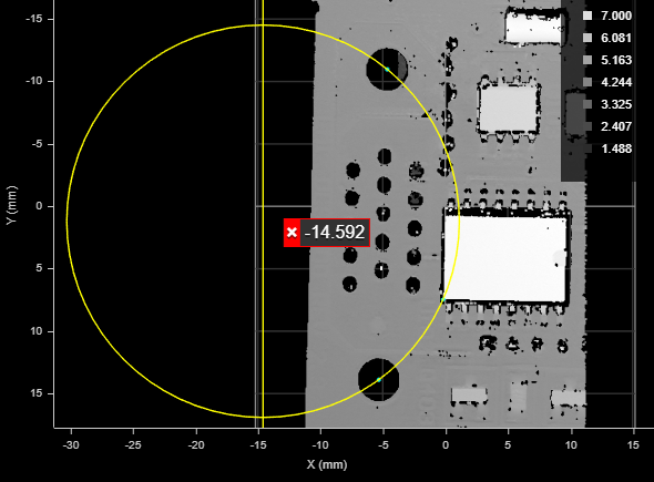
Circle generated from the center points of the two holes and the corner of the chip (cyan points).
(The corner is the intersect point resulting from the Feature Intersect tool,
taking the left vertical and lower horizontal line edges of the chip as input.)
The X, Y, and Z measurements return the center of the circle. The X, Y, and Z Angle measurements return arbitrary values.
| Inputs | Type-Related Parameters |
|---|---|
|
Input The Surface or Profile input.
Anchor X, Anchor Y, Anchor Z The X, Y, and Z offsets the tool will apply to the generated circle.
Point 1, Point 2, Point 3 The three Point geometric features the tool uses as the center of the circle. |
None. |
Circle from point and plane
The Circle from point and plane output type generates a circle using Point and Plane geometric features and a user-defined radius. The circle is on the Plane received as input.
| Inputs | Type-Related Parameters |
|---|---|
|
Input The Surface or Profile input.
Anchor X, Anchor Y, Anchor Z The X, Y, and Z offsets the tool will apply to the generated circle.
Point The Point geometric features the tool uses as the center of the circle.
Plane The Point geometric features the tool uses as the center of the circle. |
Radius The radius of the circle. |
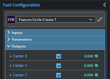
Outputs
Most tools provide measurements, geometric features, or data as outputs.
Outputs section with a measurement expanded to show user-configurable decision min/max fields and an external ID
You configure the Min and Max parameters by expanding the measurement in the Outputs section. In order for a measurement to return a Pass decision, the measurement must be between maximum and minimum values; the range is inclusive.
For information specific to the different output types, see Output Types.
| Measurement |
|---|
|
Center X, Center Y, Center Z The X, Y, and Z positions of the center of the circle. |
|
Radius The radius of the circle. |
| Z Offset
The Z position of the intersection between the circle plane and the Z axis. |
|
Distance The distance from the origin to the circle plane. |
|
Normal X, Normal Y, Normal Z The X, Y, and Z normal vectores of the circle. |
| Type | Description |
|---|---|
|
Circle |
The generated Circle geometric feature. For more information, see Output Types. |