Mesh Plane

|
This tool is only intended for use with G2 sensors. |
The Mesh Plane tool takes in Mesh scan data (produced by the Surface Mesh tool and some other Mesh tools) and returns measurements on the plane fitted within the region of interest, such as deviations of the data points relative to the plane. The tool also returns a Plane geometric feature that can be used as input by the Mesh Projection tool (see Mesh Projection). Finally, the tool returns front and back Surface data extracted from the plane: you can apply any built-in or custom GDK-based tools to the resulting data. This means that with 360-degree scan data, you can, for example, apply measurements to the sides or bottoms of your target, rather than just the top.
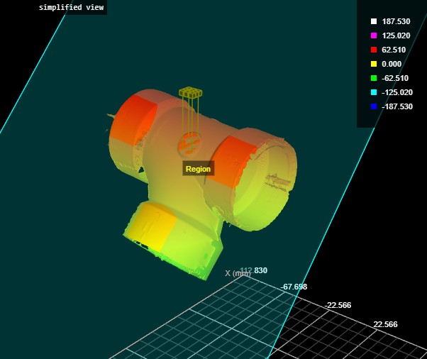
Mesh data with a region placed on a circular flat area. The plane fitted to the data in this region is shown in cyan.
The Front Surface data output is rotated by the plane's X, Y, and Z rotation.
Inputs
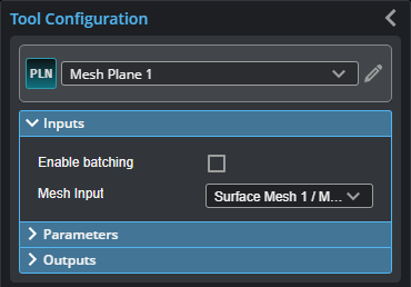
You configure the tool's inputs in the expandable Inputs section.
| Name | Description |
|---|---|
| Enable Batching |
For more information on arrays, batching, and aggregating, see Arrays, Batching, and Aggregation. |
|
Mesh Input |
The data the tool applies measurements to or processes. |
Parameters
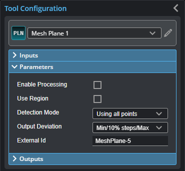
You configure the tool's parameters in the expandable Parameters section.
| Parameter | Description |
|---|---|
| Enable Processing | Enables processing. |
| Use Region | When enabled, displays region settings. |
| Region | Region settings. |
|
Detection Mode |
The plane detection mode. One of the following: With Largest Area With Maximum Distance With Minimum Distance Chooses the plane at the maximum or minimum distance in the region, respectively, from the 0 origin. Use these options when more than one plane fit is possible in the region. Works in conjunction with Search Direction. Using all points Uses all data points of the scan data in the region. |
|
Search Direction |
The search direction the tool will use to fit a plane. For example, when Search Direction is set to +Z, the tool starts searching from origin Z = 0 and moves along the positive Z axis. This parameter is only useful when Plane Detection Mode is set to one of the following:
The corresponding surface normals are taken into account in the processing so that the uninvolved points can be sorted out relatively quickly and safely. The fixed search angle is 45 degrees around the set direction. When Search Direction is set to Input Direction, the tool displays additional parameters: Tilt Angle and Direction Angle. Tilt Angle - The angle between the Z axis and the vector. Direction Angle - The vector is projected onto the XY plane and then rotated around the X axis. Specifically: X = sin(TiltAngle) * cos(DirectionAngle) Y = sin(TiltAngle) * sin(DirectionAngle) Z = cos(TiltAngle) |
|
Output Deviation |
Determines which deviations are output as measurements, which can be a combination of minimum and maximum, and a set of Deviation (x %) measurements (with the specified step between them). Can also be set so that no deviations are output. Use this to get a rough idea of the distribution of the deviation values (or a histogram of the deviations). |
|
External ID |
The external ID of the tool that appears in GoHMI Designer. For more information, see GoHMI and GoHMI Designer. |
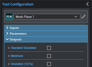
Outputs
Most tools provide measurements, geometric features, or data as outputs.
| Measurement |
|---|
|
Standard Deviation The standard deviation of the data points from the fitted plane. |
|
Minimum Maximum The minimum and maximum error of the data points from the fitted plane, respectively. |
|
Deviation (x%) Deviations of the data points from the fitted plane, sorted into stepped percentiles. You set number of steps using the Output Deviation parameter. |
| Type | Description |
|---|---|
|
Plane |
A plane geometric feature. |
|
|
For more information on geometric features, see Geometric Features. |
| Type | Description |
|---|---|
|
Front Surface |
Surface data representing the front of the meshed target. |
|
Back Surface |
Surface data representing the back of the meshed target. |
|
Difference Surface |
A Surface output that shows the fit error at each point in the height map. |