Surface Filter

The Filter tool provides several common vision processing filters that you can apply to surface data, as well as two "cropping" filters that output a subset of the surface data, letting you pre-process scan data to get more repeatable measurements. Any Surface or Feature tool can use the resulting filtered surface data as input.

For a list of the filters, see Filters.

The Filter tool provides no measurements or decisions, as its only purpose is to output processed surface data.

A limited set of filters is also available on the Scan page. These filters let you process scan data without needing to add tools. This can be useful if you are using a sensor mostly as an acquisition device.

For information on adding, managing, and removing tools, as well as detailed descriptions of settings common to most tools, see Tool Configuration.
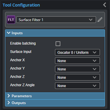
Inputs

You configure the tool's inputs in the expandable Inputs section.

To use a measurement as an anchor, it must be enabled and properly configured in the tool providing the anchor. For more information on anchoring, see Measurement Anchoring.

Inputs
Name Description
Enable Batching

When Enable Batching is checked, the tool takes an array as input and processes each surface in the array individually. There is no limit to the size of the array, other than the processing limitations of the sensor.

For more information on arrays, batching, and aggregating, see Arrays, Batching, and Aggregation.

Surface Input

The data the tool applies measurements to or processes.

Anchor X

Anchor Y

Anchor Z

The X, Y, or Z measurement of another tool that this tool uses as a positional anchor. Positional anchors are optional.

Anchor Z Angle

The Z Angle measurement of another tool to use as a rotational anchor for this tool. Rotational anchors are optional.
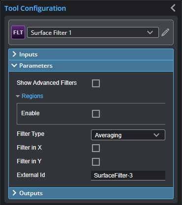
Parameters

You configure the tool's parameters in the expandable Parameters section.

Parameters
Parameter Description

Show Advanced Filters

When enabled, displays advanced filters in Filter Type (see below), in addition to the standard filters (Gap Filling, Median, Averaging, and Decimation).

Regions

When expanded, displays the region- and mask-related settings.

Enable

Enables regions and displays the region- and mask-related settings (see below).

Mask Mode

Number of Regions

Region Type {n}

Region {n}

When you enable regions (see above), the tool displays additional settings related to the region type. For details on the regions supported by this tool and their settings, see Flexible Regions.

For general information on regions and the difference between standard and "flexible" regions, see Regions.


Use Intensity

If enabled, the tool uses intensity data instead of Surface data. Only usable if Acquire Intensity is enabled on the AcquireScan page during scanning. Only available in the advanced filters (see above); for information on the available filters, see Filters.

If disabled, the tool filters using Surface data; intensity data corresponding to filtered heightmap data will also be removed.

For more information on scan modes, see Scan Modes and Intensity.

Units

Specifies whether filters use data points (pts) or millimeters (mm). Not available with all filters.

Filter Type

The type of the filter. For information on the available filters, see Filters.

Preserve Data Outside Region

Enable this setting when Mask Mode is set to Include Data in Region to include data outside the region in the Filtered Surface data output. Otherwise, the Filtered Surface data output only includes the data in the region.

This setting is only displayed if regions are enabled.

Threshold

The threshold that the filter uses. (Not available on all filters.)

Symmetry

One of the following: Symmetrical, Horizontal, or Vertical. (Not available on all filters.)

Kernel Size

The kernel size that the filter uses. (Not available on all filters.)

Filter in X

Filter in Y

These parameters enable filtering along the X and the Y axis, respectively. Set the corresponding window sizes in X Windows Size and Y Window Size.

The filter window sizes are specified in millimeters (and additionally, in the tools, in data points). To calculate the number of data points that a window covers when the units are millimeters, use the following calculation:

  • User-specified window size divided by the X spacing interval (that is, the number of millimeters per point) on the Spacing tab in the Sensor panel. (For more information on spacing intervals, see Uniform Spacing.)
  • With the exception of the gap filling filter, round the result of the division to the nearest integer value. With the gap filling filter, filling is performed within the provided window size.

For example, if you set the size of the filter's window to a value between 1.5 mm and 2.49 mm (inclusively), and the X spacing interval is set to 1 mm, the filter covers 2 data points. A filter window size from 2.5 mm to 3.49 mm results in a filter covering 3 data points.

External ID

The external ID of the tool that appears in GoHMI Designer. For more information, see GoHMI and GoHMI Designer.

The following filters are available in the Filter tool. Filters described below as advanced are only displayed if Show Advanced Filters is enabled.
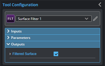
Filters
Name Description

Gap Filling

Fills in missing data using information from the nearest neighbor data points, for example, when data is missing due to occlusions. Gap filling also fills gaps where no data is detected, which can be due to low surface reflectivity, for example dark or specular surface areas, or to actual gaps in the surface. The values in Filter in X and Filter in Y represent the maximum gaps the sensor will fill. Wider gaps are not filled.

Gap filling works by filling in missing data points using either the lowest values from the nearest neighbors or linear interpolation between neighboring values (depending on the Z difference between neighboring values), in the specified window. The sensor can fill gaps along both the X axis and the Y axis.

In Profile mode, gap filling is limited to the X axis.

Median

Substitutes the value of a data point with the median calculated within the window or windows set in X Window Size or Y Window Size around the data point. If the number of valid (non-null) data points in the window is even, the median value is simply the value in the center of the sorted list of values. If the number of valid points is odd, the average of the two values in the center is used instead.

Missing data points will not be filled with the median value calculated from data points in the neighborhood.

With an odd window size, the output is at the center of the window. With an even window size, the output is 0.5 pixels to the right of the center (that is, using window / 2-1 values from the left, and window / 2 from the right.

Averaging

Substitutes a data point value with the mean value of that data point and its nearest neighbors within the window or windows set in X Window Size or Y Window SizeX smoothing works by calculating a moving average across samples within the same profile. Y smoothing works by calculating a moving average in the direction of travel at each X location.

If both X and Y smoothing are enabled, the data is smoothed along X axis first, then along the Y axis.

Missing data points will not be filled with the mean value calculated from data points in the neighborhood.

Decimation

Decimation reduces the number of data points along the X or Y axis by choosing data points at the end of a specified window around the data point. For example, by setting X Window Size to 0.2, only points every 0.2 millimeters will be used. The filter generates points starting from the leftmost edge of the scan data, stepping in equal steps away from that side.

Gaussian (advanced)

A Gaussian filter. Set the Sigma, Units, and Preserve Data Outside Region parameters as required.

Opening (advanced)

Erosion followed by dilation.

Closing (advanced)

Dilation followed by erosion.

Erosion (advanced)

Applies an erosion filter. Lets you specify the direction of the erosion; one of the following:

  • Horizontal
  • Vertical
  • Symmetrical

Dilation (advanced)

Applies a dilation filter. Lets you specify the direction of the dilation; one of the following:

  • Horizontal
  • Vertical
  • Symmetrical

Morph Gradient (advanced)

Applies a morphological gradient. The difference between dilation and erosion.

Sobel Magnitude (advanced)

Applies a Sobel magnitude filter.

Lets you specify the direction of the filter; one of the following:

  • Horizontal
  • Vertical
  • Symmetrical

Laplacian (advanced)

Applies a Laplacian filter. Useful for detecting areas of distinct edges. Uses the following kernel:

Negative (advanced)

Inverts the height or intensity values in the scan data. When Use Nulls is enabled, null values in the input are replaced by the highest height value.

Equalize (advanced)

Normalizes the norm or value range of an array.

Binarize (advanced)

Sets height values to a fixed value for each point that is present in the data. Can be used with a region Z offset to threshold points above/below a Z value.

When Use Intensity is enabled, the tool sets data points with an intensity value over

Percentile (advanced)

Limits the scan data to points between the values you set in High Percentile and Low Percentile, which are displayed when you choose this option.

Relative Threshold (advanced)

Crops scan data based on user-specified minimum and a maximum heights. Use Reference Region to set the heights relative to a reference region.

Crop only (advanced)

Crops the scan data to the user-defined region.

Outputs

Most tools provide measurements, geometric features, or data as outputs.

Data
Type Description
Filtered Surface

The filtered data, available for use as input in the Stream drop-down in other tools.