Aligning Sensors to 6 Degrees of Freedom

|
The tools described in the following sections are only intended to be used with G2 sensors. |

|
Performing alignment using the Surface Align Ring or Surface Align Wide tools (which results in 6 degrees of freedom) involves considerable setup effort. First, the 6 DoF alignment targets are more difficult to manufacture than an alignment bar and require a very high degree of accuracy; 3D printed alignment targets are not usually sufficiently accurate. Second, the alignment tools have many parameters that must be properly configured to successfully perform an alignment. |
|
|
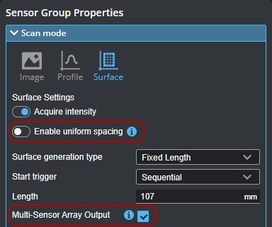
Before scanning the alignment target, remember to uncheck Enable uniform spacing in the Scan mode section on the Scan page. Also enable Multi-Sensor Array Output.
|
|
|
Sensors must not previously have been aligned using the alignment routine on the System > Alignment page. This is indicated by "Not Aligned" on that page. If necessary, click Clear Alignment.
|

Aligning a system of sensors to 6 degrees of freedom involves the use of one of two Surface measurement tools (Surface Align Wide or Surface Align Ring). These tools create a set of transformations and store them in a configuration file. The resulting alignment is more accurate compared to the other methods available on the Alignment panel, and includes compensations for X angle rotations. Note that in order to apply the transformations to scan data, you must use a "stitching" tool that corresponds to the tool used to create the transformations.
-
Surface Align Wide: Use this tool if the sensors are in a wide (that is, side-by-side) layout. Sensors may be slightly angled on the Y axis, that is, in an arc above the target. Sensors must be on the same side as the target: no data is supported on the other side. The tool is designed for up to eight sensors. The tool aligns to a multi-column truncated pyramid plate alignment target to produce the transformations necessary to stitch scans of production targets from individual sensors into a single frame of Surface scan data. In a single-sensor system, you can also use the tool to compensate for X angle rotation. (Note that in a single-sensor system, Y offset is not calculated or used.) For more information, see Wide Layouts (Surface Align Wide Tool). The workflow / data flow is as follows:

-
Surface Align Ring: Use this tool if the sensors in a multi-sensor system are in a ring or partial ring layout. The tool aligns to a double-sided truncated pyramid alignment target to produce the transformations necessary to stitch scans of production targets into a single frame of Mesh scan data. For more information on performing this type of alignment, see Ring Layouts (Surface Align Ring Tool). The workflow / data flow is as follows:
 .
.
Both tools produce configuration files, and can optionally load previously saved configuration files, which is useful if you need to set the system up again. When you run the tools on a PC, the tools store the configuration files in C:\GoTools\SurfaceAlign\. On a GoMax device, the tools store the configuration files on the device.