Profile Circle Radii
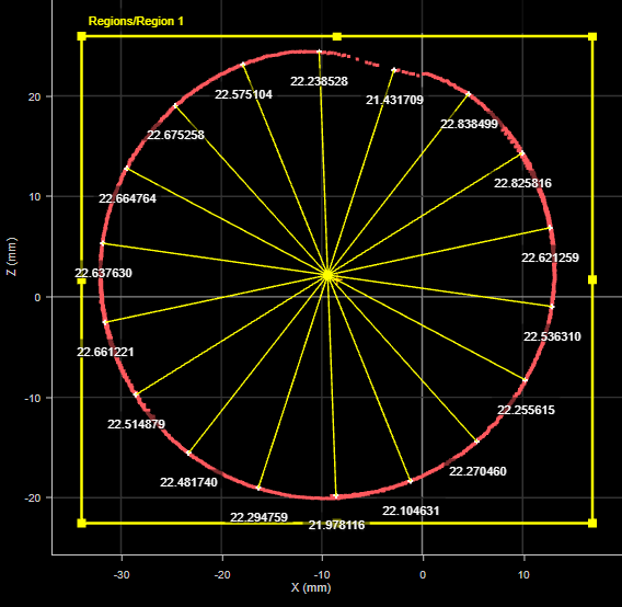
The Profile Circle Radii tool lets you measure radii and diameters at specified angle steps, given a specified center point. The tool draws rays from the center point and returns radii or diameter measurements for each ray. The center point comes from either the center of a bounding box or a point geometric feature from another tool. The tool also provides settings to compensate for missing data and for rough surfaces or noise.
For example, in the following scan of an exhaust pipe by a four-sensor system, the tool is showing a shorter radius measurement at roughly 70 degrees that indicates a dent in the pipe.
For information on adding, managing, and removing tools, as well as detailed descriptions of settings common to most tools, see Tool Configuration.
Inputs
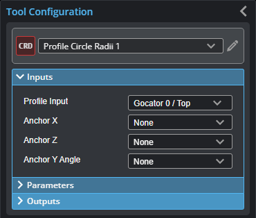
You configure the tool's inputs in the expandable Inputs section.

|
To use a measurement as an anchor, it must be enabled and properly configured in the tool providing the anchor. For more information on anchoring, see Measurement Anchoring. |
| Name | Description |
|---|---|
|
Profile Input |
The data the tool applies measurements to or processes. |
|
Anchor X or Anchor Z |
The X or Z measurement of another tool that this tool uses as a positional anchor. Positional anchors are optional. |
|
Anchor Y Angle |
The Y angle measurement of another tool that this tool uses as a rotational anchor. Rotational anchors are optional. |
| Center | The point geometric feature output by another tool that the Circle Radii tool uses as the center point from which rays are drawn to search for data points. The parameter is only available when Center Selection is set to Feature Input. |
Parameters
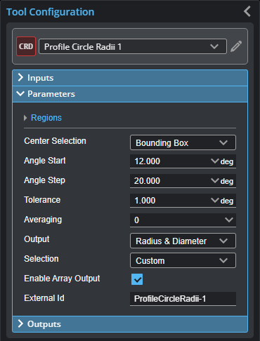
You configure the tool's parameters in the expandable Parameters section.
| Parameter | Description |
|---|---|
|
Regions |
When expanded, displays the region- and mask-related settings. |
|
Enable |
Enables regions and displays the region- and mask-related settings (see below). |
|
Mask Mode Number of Regions Region Type {n} Region {n} |
When you enable regions (see above), the tool displays additional settings related to the region type. For details on the regions supported by this tool and their settings, see Flexible Regions. For general information on regions and the difference between standard and "flexible" regions, see Regions. |
|
Center Selection |
The source for the point geometric feature the tool uses as a center point. One of the following: Bounding Box – Uses the center of the bounding box that encloses the scan data. If regions are enabled (Enable in the Regions expander is checked), the tool places a bounding box only around the data in the region. If Enable is unchecked, the tool places a bounding box around all scan data; this will include any outliers in the bounding box, which could produce an undesired center point. Feature Input – A point geometric feature provided by another tool, such as the center point from a Circle tool. |
|
Angle Start Angle Step |
Angle Start: The angle at which ray steps start. Angle Step: The angle step in degrees. The following shows how these settings work together:
The tool searches for a data point at each angle step and returns the radius from the center point or the diameter. |
|
Tolerance |
If no data point is found at the angle step, the tool searches within the specified number of degrees to each side of the step to find a data point. Useful to compensate for gaps in the data.
The graphic above shows how the tool searches to each side of the angle step until it finds a data point (circled and in yellow). |
|
Averaging |
The number of data points to each side of the point the tool uses to average. Use this to compensate for noise or rough surfaces.
The graphic above shows how the tool averages the data point at the angle step with the number of data points specified in Averaging to each side of the angle step, replacing the original data point with the average (circled and in yellow). |
|
Output |
Selects whether to output the radius, diameter, or both for each step. |
|
Selection |
Lets you quickly enable or disable all measurements. |
|
Enable Array Output |
When this parameter is checked, the tool outputs arrays containing the radius and diameter measurements. If the parameter is disabled, measurements are output for the radius or diameter at each step. |
|
External ID |
The external ID of the tool that appears in GoHMI Designer. For more information, see GoHMI and GoHMI Designer. |


Outputs
All tools provide measurements, geometric features, or data as outputs.
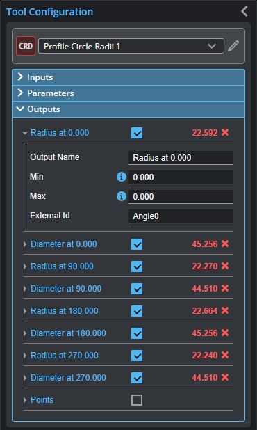
Outputs section with a measurement expanded to show user-configurable decision min/max fields and an external ID
You configure the Min and Max parameters by expanding the measurement in the Outputs section. In order for a measurement to return a Pass decision, the measurement must be between maximum and minimum values; the range is inclusive.
|
|
If you check Enable Array Output in the tool's parameters, the tool outputs radius and diameter measurements in arrays, called Radius and Diameter, respectively. Otherwise, individual measurements are output, such as "Radius at 90.000," "Radius at 180," and so on. |
| Measurement | Illustration |
|---|---|
|
Radius at {angle} Returns the radius at {angle}. |
|
|
Diameter at {angle} Returns the diameter at {angle}. |
|


| Type | Description |
|---|---|
|
Points |
An array of the points at the end of the rays. |