Profile Dimension
The Dimension tool provides Width, Height, Distance, Center X, and Center Z measurements.
For information on adding, managing, and removing tools, as well as detailed descriptions of settings common to most tools, see Tool Configuration.
Inputs
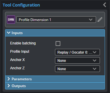
You configure the tool's inputs in the expandable Inputs section.

|
To use a measurement as an anchor, it must be enabled and properly configured in the tool providing the anchor. For more information on anchoring, see Measurement Anchoring. |
| Name | Description |
|---|---|
| Enable Batching |
For more information on arrays, batching, and aggregating, see Arrays, Batching, and Aggregation. |
|
Profile Input |
The data the tool applies measurements to or processes. This tool can optionally take an array as input. If Enable Batching is disabled and the passed array contains more than two elements, GoPxL displays an error. For more information, see Arrays, Batching, and Aggregation. |
|
Anchor X or Anchor Z |
The X or Z measurement of another tool that this tool uses as a positional anchor. Positional anchors are optional. |
Parameters
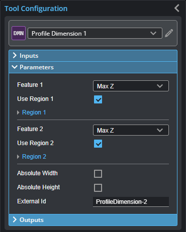
You configure the tool's parameters in the expandable Parameters section.
| Parameter | Description |
|---|---|
|
Feature 1 Feature 2 |
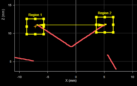
The Feature 1 and Feature 2 settings represent the two features the tool uses to perform measurements. For each, one of the following:
For more information on feature points, see Feature Points. |
|
Use Region 1 Use Region 2 |
When enabled, displays Region parameters (see below). When disabled, the tool uses all data. |
|
Region 1 Region 2 |
The region to which the tool's measurements will apply. For more information, see Regions. |
|
Absolute Width Absolute Height (Width and Height measurements only) |
Determines if the result will be expressed as an absolute or a signed value. |
|
External ID |
The external ID of the tool that appears in GoHMI Designer. For more information, see GoHMI and GoHMI Designer. |
Outputs
All tools provide measurements, geometric features, or data as outputs.
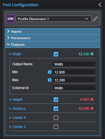
Outputs section with a measurement expanded to show user-configurable decision min/max fields and an external ID
You configure the Min and Max parameters by expanding the measurement in the Outputs section. In order for a measurement to return a Pass decision, the measurement must be between maximum and minimum values; the range is inclusive.
| Measurement | Illustration |
|---|---|
|
Width Determines the difference along the X axis between two feature points. The difference can be calculated as an absolute or signed result. The difference is calculated by: Width = Feature 2X position – Feature 1X position
|
|
|
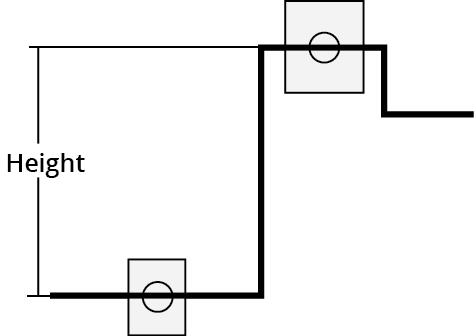
Height Determines the difference along the Z axis between two feature points. The difference can be expressed as an absolute or signed result. The difference is calculated by: Height = Feature 2Z position – Feature 1Z position |
|
|
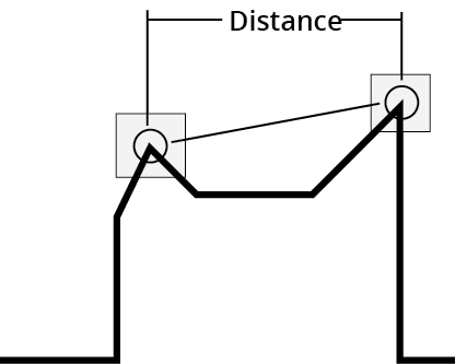
Distance Determines the direct, Euclidean distance between two feature points. |
|
|
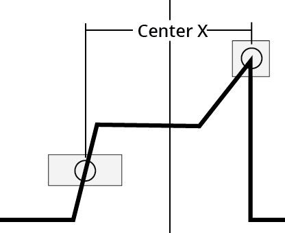
Center X Finds the average location of two features and measures the X axis position of the average location |
|
|
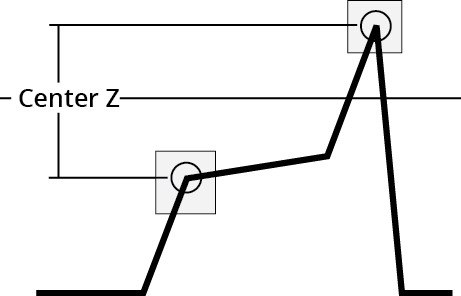
Center Z Finds the average location of two features and measures the Z axis position of the average location. |
|