Profile Template Matching
The Profile Template Matching tool lets you align a profile to a "master" template profile you create in the tool (a "golden template"), compensating for movement of the target from frame to frame. As a result, you can perform measurements on a "stabilized" profile.
The tool returns measurements that represent differences between the profile and the master, letting you perform simple defect detection and location from within the tool.
The tool also outputs an aligned profile that other Profile measurement tools can use as input. Finally, the tool produces a "difference" profile on which you can similarly perform measurements.
In the data viewer, the profiles are rendered using different colors.
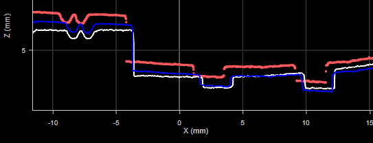
The master profile is rendered in white. The aligned profile is rendered in blue. The current profile is rendered in red.
Note that in the image above, the tool is performing only a rough alignment to ensure that the different profiles are clearly visible. Typically, the aligned profile will be on top of the master profile.
The actual colors that are used for aligned and difference profiles outputs, as opposed to the profiles toggled with the Display Master and Display Aligned Profile parameters, will depend on how each profile's color is configured in the Displayed Outputs panel.
For information on adding, managing, and removing tools, as well as detailed descriptions of settings common to most tools, see Tool Configuration.
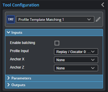
Inputs
You configure the tool's inputs in the expandable Inputs section.

|
To use a measurement as an anchor, it must be enabled and properly configured in the tool providing the anchor. For more information on anchoring, see Measurement Anchoring. |
| Name | Description |
|---|---|
| Enable Batching |
For more information on arrays, batching, and aggregating, see Arrays, Batching, and Aggregation. |
|
Profile Input |
The data the tool applies measurements to or processes. |
|
Anchor X or Anchor Z |
The X or Z measurement of another tool that this tool uses as a positional anchor. Positional anchors are optional. |
If no profile alignment is performed (both Coarse Align and Fine Align are disabled), for example, if the targets are sufficiently fixed from profile to profile, the following measurements return 0.000:
- Transform X
- Transform Z
- Transform Y Angle
Master Compare must be enabled for the following measurements; otherwise, they return Invalid values:
- Max Height Difference
- Max Difference Position X
- Max Difference Position Z
- Standard Deviation
- Difference Average
- Difference Sum
- Variance
- Matching Score
Also, for these “master compare” measurements, if the profile has been aligned to the master (either Coarse Align or Fine Align is enabled), the measurements compare the aligned profile and the master. If the profile has not been aligned (both alignment parameters are disabled), the measurement compares the original (unaligned) profile and the master.
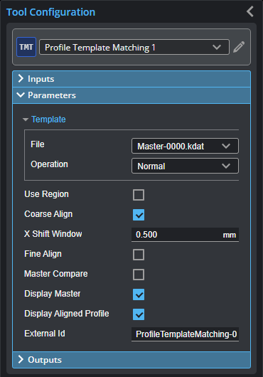
Parameters
You configure the tool's parameters in the expandable Parameters section.
| Parameter | Description |
|---|---|
| Template |
When expanded, displays File and Operation parameters. |
|
File |
A list of templates available to the tool. The template containing the profile the tool uses as a master profile for alignment and comparisons. Use the Operation parameter to add and remove templates to this list. |
|
Operation |
Provides operations related to profile template files (masters). One of the following:
|
|
Use Region |
Whether the tool uses a user-defined region to perform matching. (The tool uses only the data profile and master data in this region to perform matching.) If this option is not checked, the tool performs matching using data from the entire active area. For more information on regions, see Regions. |
|
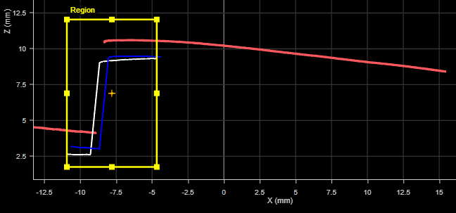
Region |
The size and position of the region in which the matching (alignment) is performed. This can be useful if only a small part of the profiles is suitable for alignment. Master comparison measurements however are applied to the entire profile (current profile and master). For example, in the following image, the tool limits matching to the data in the match region. But the measurement (Max Height Difference in this case) is calculated on the data outside the region.
|
|
Coarse Align
|
When enabled, shows the X Shift Window parameter. Use this setting by itself if you expect targets will only move along the X and Z axes (that is, you don’t expect rotation). Otherwise, when combined with Fine Align, it provides a good initial start position for fine alignment. |
|
X Shift Window |
The maximum distance on the X axis the tool can move the current profile in order to align it. Should be set to the maximum amount the part is expected to shift left or right. (Enabled using the Coarse Align parameter.) |
|
Fine Align |
When enabled, lets you set the Max Iteration and Match Window parameters for fine alignment. This alignment method is more accurate than coarse alignment but takes more time to run. |
|
Max Iteration |
The maximum number of iterations the tool uses to perform fine alignment of the profile to the master. |
|
Match Window |
The region in which points are evaluated for a match. It there’s a larger difference between the current profile and the master than the match window size, it would ignore the point. |
|
Master Compare |
Causes the tool to compare the current profile to the master profile and return results in some of the tool’s measurements. (See list above.) When disabled, the measurements that compare the profile to the master return invalid values. |
|
Difference Profile Median Size |
Defines the size of the window the tool uses to smooth out noise in the Difference Profile data output. |
|
Tolerance |
The difference tolerance for the master comparison. |
|
Display Master |
Displays the Master template (white profile). |
|
Display Aligned Profile |
Displays the aligned (blue profile). |
|
External ID |
The external ID of the tool that appears in GoHMI Designer. For more information, see GoHMI and GoHMI Designer. |
Outputs
All tools provide measurements, geometric features, or data as outputs.
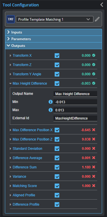
Outputs section with a measurement expanded to show user-configurable decision min/max fields and an external ID
You configure the Min and Max parameters by expanding the measurement in the Outputs section. In order for a measurement to return a Pass decision, the measurement must be between maximum and minimum values; the range is inclusive.
| Measurement |
|---|
|
Transform X Transform Z The distance the profile has shifted on the X and Z axis after alignment to the master, respectively. |
|
Transform Y Angle The rotation of the profile around the Y axis after alignment. |
|
Max Height Difference The maximum height difference between the profile and the master. |
|
Max Difference Position X Max Difference Position Z The X and Z positions of the maximum height difference between the profile and the master. |
|
Standard Deviation The standard deviation between the profile and the master. |
|
Difference Average The average difference on the Z axis between the profile and the master. |
|
Difference Sum The sum of the differences on the Z axis between the profile and the master. |
|
Variance Returns the variance of a difference profile calculated by subtracting the current profile from the master. |
|
Matching Score Returns a value between 0 and 1 that is the is the percentile of standard deviation of a difference profile (calculated by subtracting the current profile from the master) from the tolerance. |
| Type | Description |
|---|---|
|
Aligned Profile |
The profile aligned to the master. |
|
Difference Profile |
A profile representing the differences between the profile and the master. Z values in the difference profile above 0 represent data points higher in the profile than in the master. Z values in the difference profile below 0 represent data points lower in the profile than in the master. Z values in the difference profile at 0 represent data points that are the same in the profile and the master. |