Surface Cylinder
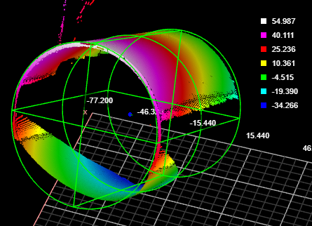
The Surface Cylinder fits a cylinder to scan data and returns measurements and geometric features related to the fitted cylinder. Unlike the Surface Stud tool, the Surface Cylinder tool does not rely on a flat surface perpendicular to the cylindrical object. Examples uses of the tool include fitting to the outside of a cylinder and fitting inside a drilled hole.
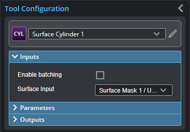
Inputs
You configure the tool's inputs in the expandable Inputs section.
| Name | Description |
|---|---|
| Enable Batching |
For more information on arrays, batching, and aggregating, see Arrays, Batching, and Aggregation. |
|
Surface Input |
The data the tool applies measurements to or processes. |
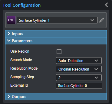
Parameters
You configure the tool's parameters in the expandable Parameters section.
| Parameter | Description |
|---|---|
|
Use Region |
When enabled, displays Region parameters (see below). When disabled, the tool uses all data. |
|
Region |
The region to which the tool's measurements will apply. For more information, see Regions. |
|
Search Mode |
Indicates the expected orientation of the cylindrical target’s axis around the Z axis. One of the following: Auto Detection – The cylindrical target can be in any orientation. Axis in X Direction or Axis in Y Direction – The cylindrical target’s axis is expected to be roughly parallel to the X or the Y axis, respectively. Variation typically must be less than +/- 3 or 4 degrees. Advanced Detection – As with Auto. Detection, the cylindrical target can be in any orientation. This mode can handle some complex scenarios, such as when trying to fit a cylinder to the inside of a hole. Processing time is greater with this search mode. |
|
Resolution Mode |
On G3 sensors, leave this set to the default Original Resolution. Determines whether the tool scales the X or Y resolution so that they are the same (a 1:1 ratio), or leaves the X and Y resolutions as the original. One of the following.
|
|
Sampling Step |
The step in data points in both directions with which the surface is sampled. Choosing a higher sampling step reduces the processing time the tool requires, but reduces fit accuracy. Useful if the surface being processed has a large number of data points. |
|
External ID |
The external ID of the tool that appears in GoHMI Designer. For more information, see GoHMI and GoHMI Designer. |
Outputs
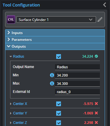
Outputs section with a measurement expanded to show user-configurable decision min/max fields and an external ID
You configure the Min and Max parameters by expanding the measurement in the Outputs section. In order for a measurement to return a Pass decision, the measurement must be between maximum and minimum values; the range is inclusive.
| Measurement |
|---|
|
Radius Returns the radius of the fitted cylinder. |
|
Center X Center Y Center Z The X, Y, and Z position of the center of a circle place in the middle of the fitted cylinder |
|
Tilt Angle The angle of the cylinder relative to the XY plane. A cylinder parallel to the XY plane has an angle of 90 degrees. |
|
Direction Angle The angle of the cylinder’s axis around the Z axis. An angle of 0 degrees is parallel to the X axis. |
|
Normal X Normal Y Normal Z These measurements return the X, Y, and Z components of the direction vector of the cylindrical target. |
| Type | Description |
|---|---|
|
Point |
A point representing the center of a circle at the midpoint of the fitted cylinder |
|
Line |
A line representing the axis of the fitted cylinder. |

|
For more information on geometric features, see Geometric Features. |