Surface Ellipse
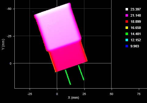
The Ellipse tool provides measurements for the major and minor axis lengths of an ellipse roughly aligned to the part's shape in the XY plane, and also for the ratio of the major and minor axis lengths and for the orientation angle of the ellipse. The tool is typically used to find the general orientation of a part, for example, potatoes on a conveyor that are longer in one dimension than the other.
Note that the ellipse fit is not the minimum area ellipse around the data. (Technically, it is the ellipse with matching moments as the data.) For surfaces with no holes, this results in an ellipse approximately the same size and orientation of the part. But for surfaces with holes, the resulting ellipse can be larger than the part.

For information on adding, managing, and removing tools, as well as detailed descriptions of settings common to most tools, see Tool Configuration.
Inputs
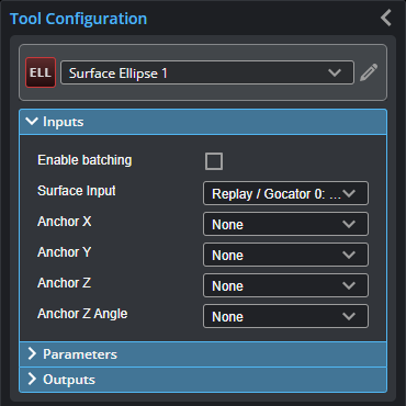
You configure the tool's inputs in the expandable Inputs section.


|
To use a measurement as an anchor, it must be enabled and properly configured in the tool providing the anchor. For more information on anchoring, see Measurement Anchoring. |
| Name | Description |
|---|---|
| Enable Batching |
For more information on arrays, batching, and aggregating, see Arrays, Batching, and Aggregation. |
|
Surface Input |
The data the tool applies measurements to or processes. |
|
Anchor X Anchor Y Anchor Z |
The X, Y, or Z measurement of another tool that this tool uses as a positional anchor. Positional anchors are optional. |
| Anchor Z Angle |
The Z Angle measurement of another tool to use as a rotational anchor for this tool. Rotational anchors are optional. |
Parameters
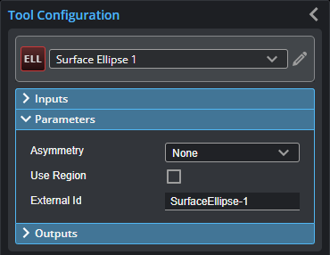
You configure the tool's parameters in the expandable Parameters section.

| Parameter | Description |
|---|---|
| Asymmetry |
Resolves the orientation of an object over 360 degrees. The possible values are: 0 – None 1 – Along Major Axis 2 – Along Minor Axis |
|
Use Region |
When enabled, displays Region parameters (see below). When disabled, the tool uses all data. |
|
Region |
The region to which the tool's measurements will apply. For more information, see Regions. |
|
External ID |
The external ID of the tool that appears in GoHMI Designer. For more information, see GoHMI and GoHMI Designer. |
Outputs
All tools provide measurements, geometric features, or data as outputs.

Outputs section with a measurement expanded to show user-configurable decision min/max fields and an external ID
You configure the Min and Max parameters by expanding the measurement in the Outputs section. In order for a measurement to return a Pass decision, the measurement must be between maximum and minimum values; the range is inclusive.
| Measurement | Illustration |
|---|---|
|
Major Determines the major axis length of an ellipse fitted to the part's area in the XY plane. |
|
|
Minor Determines the minor axis length of an ellipse fitted to the part's area in the XY plane. |
|
|
Ratio Determines the minor/major axis ratio of an ellipse fitted to the part's area in the XY plane. |
|
|
Z Angle Determines the orientation angle of an ellipse fitted to the part's area in the XY plane. |
|
| Type | Description |
|---|---|
| Center Point |
The center point of the fitted ellipse. |
| Major Axis Line | A line representing the major axis of the fitted ellipse. |
| Minor Axis Line | A line representing the minor axis of the fitted ellipse. |

|
For more information on geometric features, see Geometric Features. |


