Surface Extend
The Extend tool creates a new surface by appending part of the previous frame's data to the current frame's data. The tool outputs the new surface data, which can be used as input by other tools.

The following shows how the tool combines data:

Data is only appended in one direction. Partial objects in the resulting surface output from the tool must be filtered out using downstream tools, for example, excluding them based on the expected area.
For information on adding, managing, and removing tools, as well as detailed descriptions of settings common to most tools, see Tool Configuration.
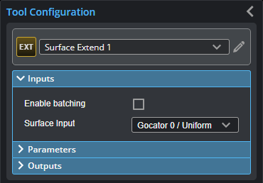
Inputs
You configure the tool's inputs in the expandable Inputs section.

|
To use a measurement as an anchor, it must be enabled and properly configured in the tool providing the anchor. For more information on anchoring, see Measurement Anchoring. |
| Name | Description |
|---|---|
| Enable Batching |
For more information on arrays, batching, and aggregating, see Arrays, Batching, and Aggregation. |
|
Surface Input |
The data the tool applies measurements to or processes. |
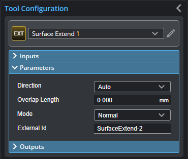
Parameters
You configure the tool's parameters in the expandable Parameters section.
| Parameter | Description |
|---|---|
|
Direction |
Determines whether the previous frame's data is appended above or below the current frame's data.
One of the following. Note that these settings depend on whether the trigger source has been set to Encoder (see Triggers) and the orientation of the sensor.
|
|
Overlap Length |
The amount, in millimeters, of the previous frame's data to append to the current frame's data. The combination will be output as tool data. Choose the overlap length to accommodate the size of your scan targets. |
| Mode |
Determines the mode of the tool. One of the following:
|
|
External ID |
The external ID of the tool that appears in GoHMI Designer. For more information, see GoHMI and GoHMI Designer. |

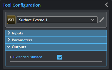
Outputs
All tools provide measurements, geometric features, or data as outputs.
| Type | Description |
|---|---|
|
Extended Surface |
Data containing an extended surface, available for use as input in the Stream drop-down in other tools. |