Surface Pattern Matching
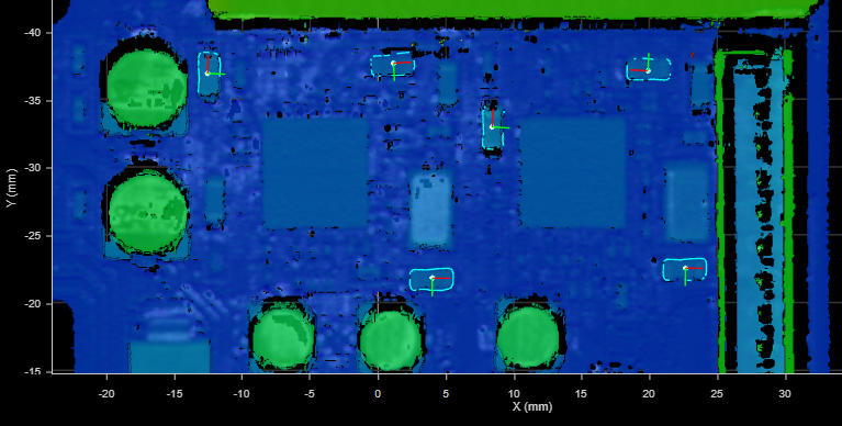
The Surface Pattern Matching tool locates parts and features by comparing 2D contours (on the XY plane) found in scan data to pattern models you have defined; note that the tool does not use height data in its algorithms. Models represent contour-based “golden parts” or “golden features.”
The tool can process multiple occurrences of a part or feature in a frame of scan data. For each matching part or feature (called an instance), the tool returns X and Y position and rotation (angle) measurements, which you can use to anchor other measurements (for more information on anchoring, see Measurement Anchoring).
The tool also returns a point and a line geometric feature for each instance, which you can use in conjunction with Surface Transform tools to shift and rotate scan data to reliably position the target.
Finally, the tool returns a match quality that you can use as a general conformity measure for matching instances (for example, checking for dents in a target), as well as a count of located instances.

|
In order to create a template for a feature on a target, you typically need to enable the Use Region checkbox to limit the tool to the contours related to that feature. After that, when running the tool to find instances of the feature, you should either modify the region to limit it to areas of the target that might contain the feature you are looking for or disable Use Region so that the tool can locate instances of the feature in all of the scan data. You can also use the Use Region parameter when creating a template to limit it to a unique portion of an outer edge of a target. |
For information on adding, managing, and removing tools, as well as detailed descriptions of settings common to most tools, see Tool Configuration.
Note that when you use the geometric features with a Surface Transform tool to transform the scan data from frame to frame, you can often avoid the need to anchor other measurements, because the transforms ensure that any features you are interested are always in the same location. This can save considerable setup time and reduce the complexity of an application. For example, in the following frames of scan data, in which a PCB shifts from frame to frame, a Surface Pattern Matching tool successfully locates the entire PCB using its outer contours and the contours of various components on the PCB, as indicated by a dark blue outline. Note the “missing” data in the second and fourth frames, on the lower right and left edges, respectively: the tool still locates the PCB, despite the occlusions.
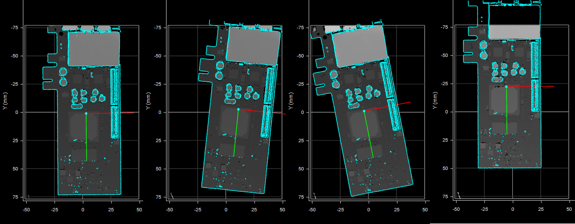
Four frames of scan data. Light blue outline represents the matching template. The first frame was used to create the template.
When the tool’s Point and Line geometric features are passed to a Surface Transform tool, the transformed scan data ensures that features are always in the same location and orientation.
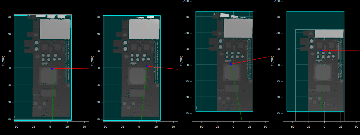
Transformed scan data of the four frames.
Other measurement tools can then be placed over the capacitors, without needing to anchor them. In the following image (the third frame, which was significantly shifted and rotated), a Surface Filter tool isolates the capacitors based on height. Subsequent tools can perform measurements on the isolated data to verify that all capacitors are present, are seated properly, and so on.

By adding multiple Surface Pattern Matching tools to a job and defining different templates for each, you can match multiple types of features or parts, for example, matching different parts moving on a conveyor, or different types of features on a single target.
Creating a Template
To create a template:
| 1. | Scan a part that is representative of a "good" part (no damage, all features are present, and so on). |
| 2. | Add an instance of Surface Pattern Matching. |
| 3. | If you need to perform pattern matching on a feature on the part, enable Use Region and position the region over the feature. |
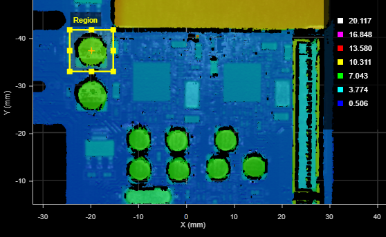
Otherwise, if you need to match the entire part, for example to orient parts from frame to frame, leave Use Region disabled to perform pattern matching on all of the scan data. This only works if no unwanted data is in the frame, such as the conveyor.
| 4. | In the Operation drop-down, choose Create. |
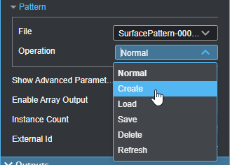
The tool creates a model and saves it either to the PC (to C:\GoTools\SurfacePatternMatching) or to the sensor. The tool also "matches" the pattern.
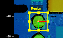
| 5. | Disable, resize, or reposition the region as necessary to match the pattern in parts you will be scanning in production. |
After creating a template, configure the tool's parameters (see below) for use during production runs.
Inputs
You configure the tool's inputs in the expandable Inputs section.
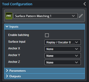

|
To use a measurement as an anchor, it must be enabled and properly configured in the tool providing the anchor. For more information on anchoring, see Measurement Anchoring. |
| Name | Description |
|---|---|
| Enable Batching |
For more information on arrays, batching, and aggregating, see Arrays, Batching, and Aggregation. |
|
Surface Input |
The data the tool applies measurements to or processes. |
|
Anchor X Anchor Y Anchor Z |
The X, Y, or Z measurement of another tool that this tool uses as a positional anchor. Positional anchors are optional. |
Parameters
You configure the tool's parameters in the expandable Parameters section.
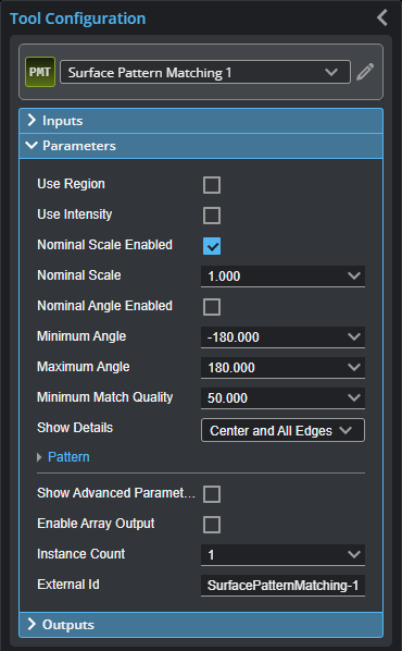
| Parameter | Description |
|---|---|
|
Use Region |
Determines whether the tool uses a user-defined region to search for matching instances, or, when first creating a template, whether the tool limits establishing template contours to the data in the ROI. |
|
Region |
Settings related to the region. For more information, see Regions. |
|
Use Intensity |
Determines whether the tool uses intensity instead of heightmap data to locate instances or create templates. |
|
Nominal Scale Enabled |
If Nominal Scale Enabled is checked, the tool displays the Nominal Scale setting and the tool uses the user-defined nominal scale. Otherwise, the tool displays Minimum Scale and Maximum Scale settings and uses the user-defined range. |
|
Nominal Scale |
The scale factor the tool requires to recognize an instance. Displayed when Nominal Scale Enabled is enabled. |
|
Minimum Scale Maximum Scale |
The minimum and maximum scale factors set the acceptable scaling range of an instance. Displayed when Nominal Scale Enabled is disabled. |
|
Nominal Angle Enabled |
If enabled, displays the Nominal Angle setting and the tool uses the user-defined nominal angle. Otherwise, the tool displays Minimum Angle and Maximum Angle settings and uses the user-defined range. |
|
Nominal Angle |
The angle the tool requires to recognize an instance. Displayed when Nominal Angle Enabled is enabled. |
|
Minimum Angle Maximum Angle |
The minimum and maximum angles allowed for the tool to recognize an instance, respectively. Displayed when Nominal Angle Enabled is disabled. |
|
Minimum Match Quality |
Minimum percentage of template contours that must match in the scan data for the tool to consider the object instance as valid. |
|
Show Detail |
Toggles whether to overlay tool details. Center only: The center of the found pattern and its XYZ axes. Center and All Edges: The center of the found pattern and its XYZ axes, as well as the outline of the full pattern template. Center and Matched Edges: The center of the found pattern and its XYZ axes, as well as the matched edges only. |
|
Pattern |
When expanded, displays parameters related to template files.
File A drop-down containing the currently available templates.
Operation The operation to perform on the currently selected template in the File drop-down. One of the following: Normal: The default value after having performed another operation. Create: Creates a new template based on the current frame of scan data. Limited to the region if Use Region is enabled. Load: Loads the currently selected template. Save: Saves contour data to the currently selected template, overwriting its contour data. Delete: Deletes the currently selected template. Refresh: Refreshes the list of templates. This is useful if you have renamed a template (using the Pattern Editor or manually in the client PC's file system). |
|
Show Advanced Parameters |
When enabled, the tool displays the following additional advanced parameters.
Sorting The sort order of instances the tool uses. One of the following:
Recognition Level The "effort" the tool will expend on recognizing an instance in scan data. Ranges from Fast to Accurate (that is, there is a trade-off between accuracy and speed). Only used during pattern matching (and not during pattern template creation).
Positioning Level How accurately the tool determines the position of the instance. Ranges from Fast to Accurate. Only used during pattern matching (and not during pattern template creation).
Match Tolerance Mode The tolerance the tool uses when attempting to match contours in the scan data to the loaded template; this is the maximum distance between the contours in the template and in the scan data. Either Pattern-based (a looser tolerance, the default), Resolution-based (a tighter tolerance), or Manual. Typically, the Pattern-based option should produce a better match quality. However, if you are getting too many false matches, try setting the mode to Resolution-based or set the value manually. The tolerances calculated from the pattern-based and resolution-based modes are displayed in the mode drop-down. Note that the resolution-based mode results in a much tighter tolerance with high resolution scan data.
Add Border Considers a drop to NULL, outside the region, as an edge. Use this when performing part detection or when there is no data around the part. If there is nothing in the region, then there will be nothing in the template either. |
|
Enable Array Output |
When Enable Array Output is disabled, the tool produces individual outputs for each instance. (For example, X 1 and Y 1 for the first instance, X 2 and Y 2 for the second instance, and so on.) When Enable Array Output is enabled, the tool produces an array for each output. For more information on arrays, batching, and aggregating, see Arrays, Batching, and Aggregation. |
|
Instance Count |
The maximum number of instances the tool will locate. If Enable Array Output is checked, this parameter is hidden. |
|
External ID |
The external ID of the tool that appears in GoHMI Designer. For more information, see GoHMI and GoHMI Designer. |
Outputs
All tools provide measurements, geometric features, or data as outputs.
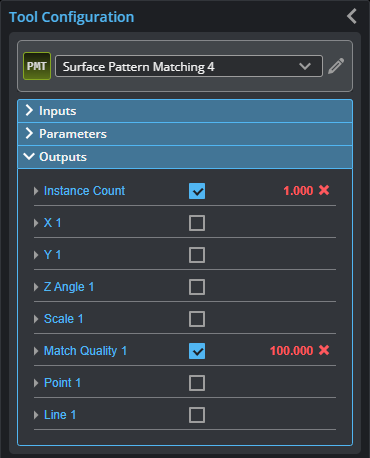
You configure the Min and Max parameters by expanding the measurement in the Outputs section. In order for a measurement to return a Pass decision, the measurement must be between maximum and minimum values; the range is inclusive.
| Measurement |
|---|
|
Instance Count Returns the number of parts or features matching the loaded template up to the value set in the Instance Count parameter. |
|
X {n} Y {n} The X and Y position of the center of matched instance {n}. |
|
Z Angle {n} The angle of matched instance {n} relative to the sensor’s coordinate system. |
|
Scale {n} The scale of matched object {n} relative to the loaded template. |
|
Match Quality {n} Percentage of matched model contours for the selected object instance. Match quality ranges from 0 to 100, with 100 being the best quality. A value of 100 means 100% of the model contours were successfully matched to the actual contours detected in the scan data. Use the Minimum Match Quality parameter to set the minimum acceptable value. |
| Type | Description |
|---|---|
|
Point |
A point representing the center of the region used when creating a template and the template’s default reference point. (Note that the reference point of a template can be changed in the model editor.) |
|
Line |
A line parallel to the X axis passing through the Point feature. |

|
For more information on geometric features, see Geometric Features. |