Surface Section
The Surface Section tool lets you define a line on a surface (a "section") from which the tool extracts a profile. You can then apply any Profile tool to the resulting profile (see Profile Measurement). A section can have any XY orientation on the surface. The resulting profile is on the XZ plane.
Using sections and the profile measurements, you can therefore use measurements that are not otherwise possible in Surface mode, for example:
- Gap and flush measurements
- Surface radius measurements (for example, rounded edges or corners)
- Intersections
- Point-to-point dimension measurements between profile features
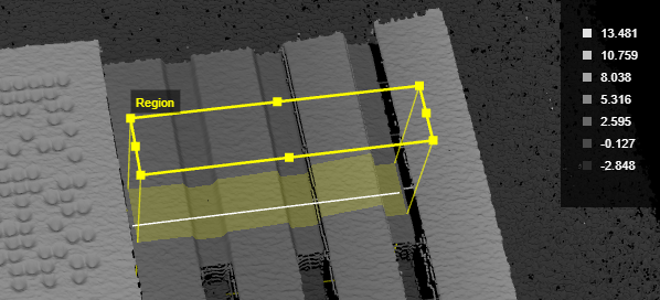
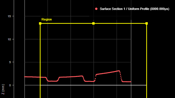
The resulting profile. The leftmost point of the profile is at the X origin. The region is positioned showing the X and Z position of the center of the region on the surface.
You can anchor the tool to some other easily identifiable feature on the scan target, which "shifts" the section in relation to that feature in case the target moves. This increases repeatability. For more information, see Measurement Anchoring.
For information on adding, managing, and removing tools, as well as detailed descriptions of settings common to most tools, see Tool Configuration.
Inputs
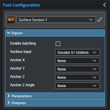
You configure the tool's inputs in the expandable Inputs section.

|
To use a measurement as an anchor, it must be enabled and properly configured in the tool providing the anchor. For more information on anchoring, see Measurement Anchoring. |
| Name | Description |
|---|---|
| Enable Batching |
For more information on arrays, batching, and aggregating, see Arrays, Batching, and Aggregation. |
|
Surface Input |
The data the tool applies measurements to or processes. This tool can optionally take an array as input. For more information, see Arrays, Batching, and Aggregation. |
|
Anchor X Anchor Y Anchor Z |
The X, Y, or Z measurement of another tool that this tool uses as a positional anchor. Positional anchors are optional. |
| Anchor Z Angle |
The Z Angle measurement of another tool to use as a rotational anchor for this tool. Rotational anchors are optional. |
|
Point 1 Point 2 |
The Point geometric features the tool uses to define the end points of the section. Only displayed if Point Mode is set to Feature Points. |
Parameters
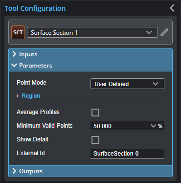
You configure the tool's parameters in the expandable Parameters section.
| Parameter | Description |
|---|---|
| Point Mode |
Selects how the tool defines the end points of the section. One of the following: User-Defined: Enables a region (see Region below) whose size, position, and rotation you define. The section is placed along the X axis in the middle of the region. Feature Points: Uses two Point geometric feature inputs as the end points of the section. |
|
Region |
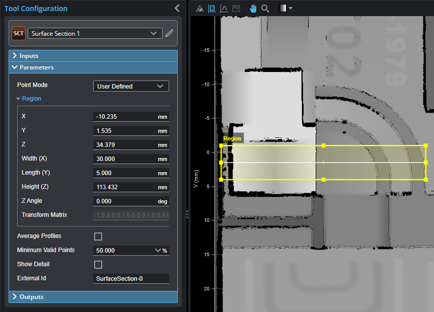
A rectangular region to define the section to extract. By default, the section is taken along the X axis of the region. The length of the region (along the Y axis) is the averaging width for the section. In the following, the region is set to a length of 5 mm and a width of 30 mm. The tool will therefore use a 5 mm averaging window, perpendicular to the X axis (width) of the region, to calculate the data point using its neighbor. If Average Profiles is enabled, the tool averages the points along the entire length of the region.
For more information, see Regions. |
|
Average Profiles |
When enabled, averages the profiles in the region to produce the section profile. Otherwise, the tool only uses the data points under the line running parallel to the X axis in the middle of the region. |
|
Minimum Valid Points |
When Average Profiles is enabled, the minimum percentage of neighboring points across the averaging width (perpendicular to the section) that need to be valid for a point to be output on the resulting profile. |
|
Show Detail |
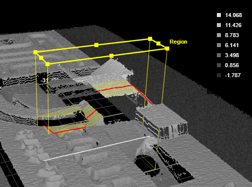
Determines whether data points (in red) are displayed under the section in the data viewer. If this setting is disabled, only the line representing the defined section is displayed. Show Details enabled:
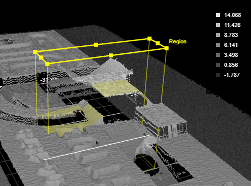
Show Details disabled:
|
|
External ID |
The external ID of the tool that appears in GoHMI Designer. For more information, see GoHMI and GoHMI Designer. |
Outputs
All tools provide measurements, geometric features, or data as outputs.
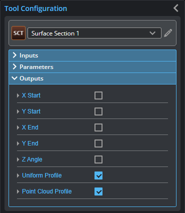
You configure the Min and Max parameters by expanding the measurement in the Outputs section. In order for a measurement to return a Pass decision, the measurement must be between maximum and minimum values; the range is inclusive.
| Measurement |
|---|
|
X Start These measurements return the X and Y position of the start of the section, respectively. |
|
X End These measurements return the X and Y position of the end of the section, respectively. |
|
Z Angle Returns the rotation of the section around the Z axis. |
| Type | Description |
|---|---|
|
Uniform Profile Point Cloud Profile |
The profile (uniform or point cloud, respectively) that the tool extracts from the surface. Available to profile tools for profile measurement. |
