Surface Bounding Box
The Bounding Box tool provides measurements related to the smallest box that contains the scan data from a part (for example, X position, Y position, width, length, etc.). The tool also lets you get the height of bounding box relative to the Z origin (typically the conveyor on which the target is sitting). This lets you determine, for example, the height of a box or other container on the conveyor as part of a product packaging process. Various settings let you easily filter out noise that can affect height, width, and length measurements.
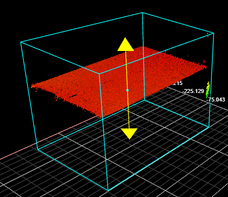
A bounding box can be vertical or rotated. A vertical bounding box provides the absolute position from which the Position centroids tools are referenced.
For information on adding, managing, and removing tools, as well as detailed descriptions of settings common to most tools, see Tool Configuration.
Inputs
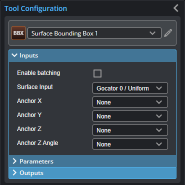
You configure the tool's inputs in the expandable Inputs section.

|
To use a measurement as an anchor, it must be enabled and properly configured in the tool providing the anchor. For more information on anchoring, see Measurement Anchoring. |
| Name | Description |
|---|---|
| Enable Batching |
For more information on arrays, batching, and aggregating, see Arrays, Batching, and Aggregation. |
|
Surface Input |
The data the tool applies measurements to or processes. This tool can optionally take an array as input. For more information, see Arrays, Batching, and Aggregation. |
|
Anchor X Anchor Y Anchor Z |
The X, Y, or Z measurement of another tool that this tool uses as a positional anchor. Positional anchors are optional. |
| Anchor Z Angle |
The Z Angle measurement of another tool to use as a rotational anchor for this tool. Rotational anchors are optional. |
Parameters
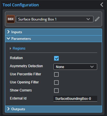
You configure the tool's parameters in the expandable Parameters section.
| Parameter | Description |
|---|---|
|
Regions |
When expanded, displays the region- and mask-related settings. |
|
Enable |
Enables regions and displays the region- and mask-related settings (see below). |
|
Mask Mode Region Type 1 Region 1 |
When you enable regions (see above), the tool displays additional settings related to the region type. For details on the regions supported by this tool and their settings, see Flexible Regions. For general information on regions and the difference between standard and "flexible" regions, see Regions. |
|
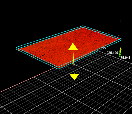
Rotation |
A bounding box can be vertical or rotated. A vertical bounding box provides the absolute position from which the part's Position centroid measurements are referenced. Check the Rotation setting to select rotated bounding box. When this setting is enabled, an Asymmetry Detection setting is displayed. |
| Asymmetry Detection |
Resolves the orientation of an object over 360 degrees. The possible values are: 0 – None 1 – Along Major Axis 2 – Along Minor Axis This setting is only visible if Rotation is checked. |
|
Use Percentile Filter |
Limits the bounding box to data points along the Z axis between the values you set in High Percentile and Low Percentile, which are displayed when you choose this option. Use this setting to obtain more "robust" height measurements. This setting is useful to exclude noise that would otherwise cause inaccurate height measurements. For example, in the following scan of a box, without excluding a small percentage of the highest data points, data points caused by noise to the upper right produces an inaccurate height measurement (from the Z origin) of the box of 406.457 mm. (The following screenshots are from a G2 sensor.)
When High Percentile is set to 99%, the highest 1 percent of data points is excluded from the placement of the bounding box, and an accurate height of the target box of 270.477 mm is returned.
|
|
High Percentile Low Percentile |
See Use Percentile Filter above. |
|
|
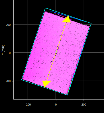
When enabled, this setting lets you set the value of Kernel Size for an opening morphological operation applied to the scan data on the XY plane, letting you achieve "robust" width and length measurements. This filter removes noise or small objects from scan data, while keeping the shape and size of the larger objects in the scan data. For example, in the following, noise along the edge at the top of the data viewer results in an inaccurate length measurement. (The following screenshots are from a G2 sensor.)
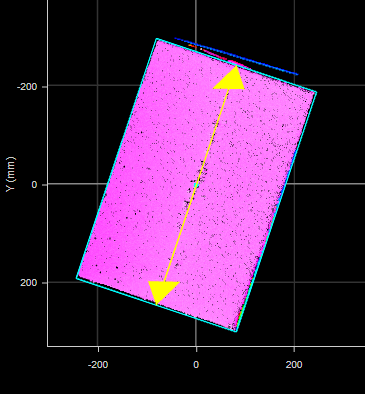
When the filter is set to an appropriately sized kernel (here, 11 points), the noise is excluded from the calculation of the bounding box, and an accurate length is returned.
Use the Diagnostics Surface on the Data tab to evaluate the impact of the open filter, to avoid removing too much data. |
| Kernel Size | See Use Opening Filter above. |
| Show Corners | When this setting is enabled, the tool outputs a Point geometric feature for each corner of the box. |
|
External ID |
The external ID of the tool that appears in GoHMI Designer. For more information, see GoHMI and GoHMI Designer. |
Outputs
Most tools provide measurements, geometric features, or data as outputs.
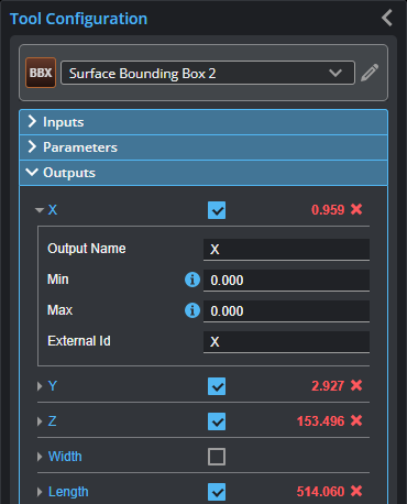
Outputs section with a measurement expanded to show user-configurable decision min/max fields and an external ID
You configure the Min and Max parameters by expanding the measurement in the Outputs section. In order for a measurement to return a Pass decision, the measurement must be between maximum and minimum values; the range is inclusive.
| Measurement | Illustration |
|---|---|
|
X Determines the X position of the center of the bounding box that contains the part. The value returned is relative to the part. |
|
|
Y Determines the Y position of the center of the bounding box that contains the part. The value returned is relative to the part. |
|
|
Z Determines the Z position of the center of the bounding box that contains the part. The value returned is relative to the part. |
|
|
Width Determines the width of the bounding box that contains the part. When the Rotation setting is disabled, the bounding box is the smallest rectangle whose sides are parallel to the X and Y axes. Width is on the X axis. When Rotation is enabled, the width is the smaller side dimension. |
|
|
Length Determines the length of the bounding box that contains the part. When the Rotation setting is disabled, the bounding box is the smallest rectangle whose sides are parallel to the X and Y axes. Length is on the Y axis. When Rotation is enabled, the length is the longer side dimension. |
|
|
Height Determines the height of the bounding box that contains the part. |
|
|
Height from 0 Determines the distance from the top of the bounding box to the Z origin (Z = 0). |
|
| Z Angle
Determines the rotation around the Z axis and the angle of the longer side of the bounding box relative to the X axis. If Rotation is not enabled, the measurement returns 90.000 degrees. In order to use this measurement for angle anchoring, you must enable Rotation; for more information on anchoring, see Measurement Anchoring. |
|


| Type | Description |
|---|---|
|
Center Point |
The center point of the bounding box. |
|
Box Axis Line |
The axis of the bounding box. |
| Corner {n} | Point geometric features representing the corners of the box. Only displayed when Show Corners is checked. |
|
|
For more information on geometric features, see Geometric Features. |