Advanced Settings
The settings in the Advanced section on the Inspect > Scan page let you configure material characteristics, camera gain, and dynamic exposure.

Material Type and Spot Detection
You can configure data acquisition to suit different types of target materials.
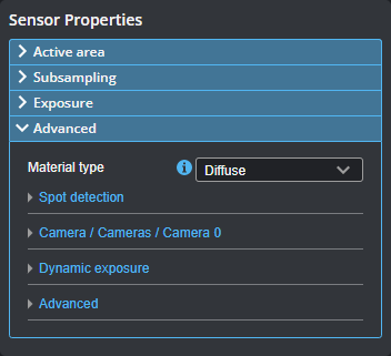
You can select preset material types in the Material type setting in the Advanced panel on the Inspect > Scan page. The Diffuse material option is suitable for most materials.
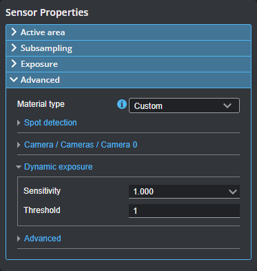
When Material type is set to Custom, you can set camera gain and modify spot detection. Some sensor models support both analog and digital gain, whereas others only support digital gain. For more information, see Spot Detection and Camera Gain.
Spot Detection
When adjusting the spot detection parameters, it's best to set the sensor to Profile mode and set the data viewer to Profile view to see the effect of changes you make. You can only adjust spot detection parameters when Material type is set to Custom.
When Materials is set to Custom, you can configure the following settings. In order to properly configure the spot-related settings, you should use Image mode (for more information, see Image Mode) to observe the laser line and spots in the data viewer. For information on spots and displaying them in the data viewer, see Spots and Dropouts.

|
Edge window, Width threshold, and Max spots are advanced parameters. You should generally not change them. |
| Setting | Description |
|---|---|
|
Threshold |
The minimum increase in intensity level between neighboring pixels for a pixel to be considered the start of a potential spot. This setting is useful for filtering false spots generated by sunlight reflection. |
|
Spot Selection |
Determines the spot selection method. For details, see Spot Selection Methods. |
|
Min width Max width |
The minimum and maximum number of pixels a spot is allowed to span along Y in the data viewer (in Image mode). This setting can be used to filter out data caused by background light if the unwanted light is wider than the laser and does not merge into the laser itself. A lower Max width setting reduces the chance of false detection, but limits the ability to detect features/surfaces that elongate the spot. Min width can help reduce small speckle noise. |
| Min sum |
Minimum total of pixel intensities over a spot. If the total of pixel values is below this value, the spot will be dropped. This can be used to exclude weak spots, but this is typically undesirable, so it is often set to 1. |
| Setting | Description |
|---|---|
|
Best |
The Best spot selection method selects the strongest or peak spot in a given column on the imager. |
|
Top or Bottom |
Top selects the topmost spot or the one farthest to the left on the imager, and Bottom selects the bottommost spot or the one farthest to the right on the imager. These options can be useful in applications where there are reflections, flying sparks, or smoke that are always on one side of the laser. |
|
None |
The None selection mode performs no spot filtering. If multiple spots are detected in an imager column, they are left as is. Note that when Uniform Spacing is disabled and Spot Selection is set to None, both Profile Dimension and Profile Position are unavailable; for more information on enabling and disabling uniform spacing, see Scan Modes and Intensity. |
|
Continuity |
The Continuity selection mode considers adjacent horizontal data points on the imager to place spots on pixels, giving preference to more complete profile segments. The setting can improve scans in the presence of reflections and noise. When you select the continuity type, you must set the Min segment size, Search window length, and Search window width parameters, which define the minimum length of the segment, as well as the length and width of the segment search window. |
Various settings can affect how the Material settings behave. For more information, Spots and Dropouts.
Camera Gain
| Setting | Description |
|---|---|
|
Camera Gain |
|
|
Analog camera gain can be used when the application is severely exposure limited, yet dynamic range is not a critical factor. Boosts the signal before conversion to digital, so it can potentially allow differentiating dark details that would otherwise be mapped to the same digital value. Not available on all sensor models. Digital camera gain can be used when the application is severely exposure limited, yet dynamic range is not a critical factor. |
Material Settings and Dynamic Exposure
You can set dynamic exposure to improve data acquisition.
The settings are in the Advanced panel on the Inspect > Scan page.

| Setting | Description |
|---|---|
|
Dynamic Exposure |
|
|
Dynamic Sensitivity controls the exposure that dynamic exposure converges to. The lower the value, the lower the exposure the sensor will settle on. The trade-off is between the number of underexposed spots and the possibility of over-exposing. Dynamic Threshold is the minimum number of spots for dynamic exposure to consider the profile point that make up the spot valid. If the number of spots is below this threshold, the algorithm will walk over the allowed exposure range slowly to find the correct exposure. Because this is slow, the parameter's value typically should be kept as low as possible, so this slow search is not used. These settings let you set tune how dynamic exposure settles on an exposure for a scan. For more information on Dynamic Exposure, see Dynamic Exposure. |
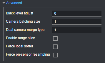
Other Advanced Settings
You should leave the settings in the Advanced expanding section unchanged unless you are told to do so by LMI support.
