Feature Intersect
The Feature Intersect tool returns the intersection of a line or plane geometric feature and a second line or plane geometric feature. For line-line intersections, the lines are projected onto the Z = reference Z line plane for features extracted from a surface, and the intersection of the lines projected onto the Y = 0 plane for features extracted from a profile. The angle measurement between the two lines is also returned. The lines the tool takes as input are generated by other tools, such as Surface Edge or Surface Ellipse.
The Feature Intersect tool's positional measurements are particularly useful as anchor sources. For example, you can easily find a corner point on a part from two edges (produced by two Surface Edge tools) and using the X and Y positions as anchor sources.
When you use these positional anchors in combination with a Z Angle anchor from tools such as Surface Edge, you can achieve extremely robust, repeatable measurements.
For more information on anchoring, see Measurement Anchoring.
The Feature Intersect tool can also generate a point geometric feature representing the point of intersection of the lines that the Feature Dimension tool can use in measurements.
See Adding a Tool for instructions on how to add measurement tools.
Inputs
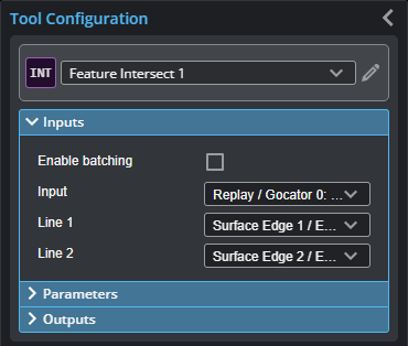
You configure the tool's inputs in the expandable Inputs section.
The tool's inputs depend on the intersection type you choose in the Intersection Type parameter. For information on the required inputs and parameters of each output type, see Feature Intersect.

| Name | Description |
|---|---|
| Enable Batching |
When Enable Batching is checked, the tool takes an array as input and processes each element in the array individually. For more information on arrays, batching, and aggregating, see Arrays, Batching, and Aggregation. |
|
Input |
The data the tool applies measurements to or processes. |
|
Line or Plane |
The geometric features the tool uses to calculate an intersect. A combination of Line or Plane geometric features, depending on the Intersection Type parameter. |
Parameters
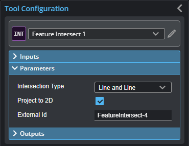
You configure the tool's parameters in the expandable Parameters section.

| Parameter | Description |
|---|---|
|
Intersection Type |
One of the following:
The intersection type determines which inputs are available in the Inputs. |
|
Project to 2D |
Only shows when Intersection Type is “Line and Line”. If checked, the intersection angle is projected to the XZ plane for Profile mode and XY plane for Surface mode. Otherwise, outputs the 3D angle. |
|
External ID |
The external ID of the tool that appears in GoHMI Designer. For more information, see GoHMI and GoHMI Designer. |
Outputs

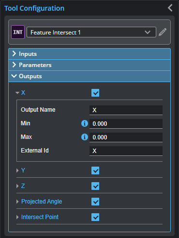
Outputs section with a measurement expanded to show user-configurable decision min/max fields and an external ID
You configure the Min and Max parameters by expanding the measurement in the Outputs section. In order for a measurement to return a Pass decision, the measurement must be between maximum and minimum values; the range is inclusive.
| Measurement | Illustration |
|---|---|
|
X Line-Line: The X position of the intersect point between the lines. Line-Plane: The X position of the intersect point between the line and the plane. Plane-Plane: The X position of the center of the line intersecting the planes. |
|
|
Y Line-Line: The Y position of the intersect point between the lines. Line-Plane: The Y position of the intersect point between the line and the plane. Plane-Plane: The Y position of the center of the line intersecting the planes. |
|
|
Z Line-Line: The Z position of the intersect point between the lines. Line-Plane: The Z position of the intersect point between the line and the plane. Plane-Plane: The Z position of the center of the line intersecting the planes. |
|
|
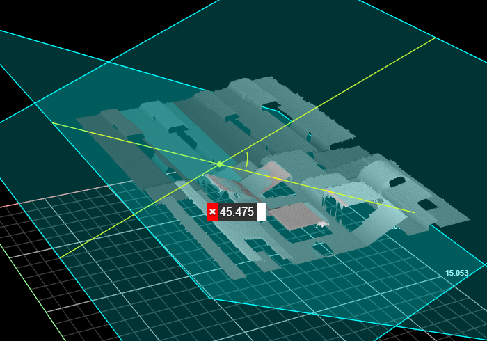
Angle or Projected Angle ( Line-Line: The angle between the lines, as measured from the line selected in Reference Feature to the line selected in Line. If Project To 2D is enabled, the output is Projected Angle. Line-Plane:The angle between the line and the perpendicular projection of the line onto the plane, as measured from the plane geometric feature selected in Reference Feature to the line selected in Line. Plane-Plane:The angle between the two planes, as measured from the plane geometric features selected in Feature 1 and Feature 2. |
In the following image, the angle is measured between two planes (the small angled surfaces facing each other in the center of the image).
|
| Type | Description |
|---|---|
|
Intersect Point |
The intersect point of the two features. |
| Intersect Line | The line representing the intersection of two planes. |


